


Chapter 1 Introduction Vmux-2100 Installation and Operation Manual
1-6 Functional Description
1.3 Functional Description
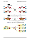
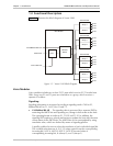
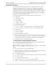
Figure 1-5 illustrates the block diagram of Vmux-2100.
Ethernet
Switch
10/100BaseT Main Link
E1/T1 Main Link
Control Port Host
Main Module
E1/T1
E1/T1
E1/T1
E1/T1
E1/T1
E1/T1
E1/T1
E1/T1
Group 1
Group 1
Group 1
Group 1
Group 2
Group 2
Group 2
Group 2
E1/T1
E1/T1
E1/T1
E1/T1
E1/T1
E1/T1
E1/T1
E1/T1
Voice Module
Voice Module
Voice Module
Voice Module
Figure 1-5. Vmux-2100 Block Diagram
Voice Modules
Voice modules include two or four E1/T1 ports which receive E1/T1 trunks from
PBXs. Every two E1 and T1 ports are referred to as a group, which receives a
separate IP address.
Signaling
Signaling information is processed according to signaling mode: CAS for E1,
Robbed Bit MF for T1, or CCS for E1 and T1.
• CAS/Robbed Bit MF – The signaling data is processed by a separate DSP by
extracting the ABCD bits and reporting any change in their status to the host.
The reporting format is similar to E1, T1 ESF and T1 SF. In addition, the
signaling DSP employs a refresh mechanism to update the host with the most
recent status of the ABCD bits. The ABCD bits can be manipulated by using
translation rules, which are defined by means of signaling profiles.
A profile enables the user to select the translation of each individual signal bit.
The available selections are A, B, C, D (value copied from the corresponding
incoming bit), NOT A, NOT B, NOT C, NOT D (inverted value of
corresponding incoming bit), 0 (always 0), and 1 (always 1).