


Vmux-2100 Installation and Operation Manual Chapter 2 Installation and Setup
AM Installation and Setup 2-3
JP16
JP14
JP11
JP13
JP8
JP12
JP5
JP7
FGND 3, 6
FGND 3, 6
NONO YES
JP10
JP1
JP9
UNBAL
UNBAL
UNBAL
UNBAL
UNBAL
UNBAL
UNB
UNB
JP6
BAL
BAL
BAL
BAL
BAL
BAL
BAL
BAL
YES
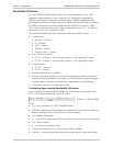
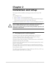
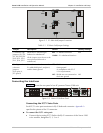
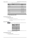
Figure 2-1. E1 Main Link Jumper Locations
Table 2-1. E1 Main Link Jumper Settings
Jumper Description Values Factory Setting
E1 interface type
jumpers, JP1, JP2,
JP5, JP6, JP8, JP9,
JP10, JP11, JP12,
JP13, JP14, JP15
Select the E1 interface type:
balanced or unbalanced.
All the jumpers must be set to the
same position (balanced or
unbalanced).
BAL – E1 balanced interface
UNBAL – E1 unbalanced interface
BAL
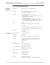
Shield ground
reference
jumpers,
JP16 (port A),
JP7 (port B)
Control connection between the
E1 cable shield (pin 3 and pin 6)
and the frame ground.
YES – Shields are connected to the
frame ground
(in compliance with ITU-T
I.431 requirements)
NO – Shields are not connected to
the frame ground
NO
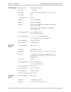
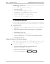
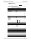
Connecting the Interfaces
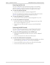
Figure 2-2 shows the rear panel of an AC-powered Vmux-2100 unit.
Vmux
2100
PS1PS2
1
LOC REM
234VC-4E11
LOC REM
234VC-4E1
1
LOC REM
POWERPOWER
234
41
32
VC-4E11
LOC REM
234VC-4E1
LOC
REM
A
ETH/E1 CONTROL
ETH
ACT LINK
TST
ALM
E1 B
Figure 2-2. Vmux-2100 Rear Panel
Connecting the E1/T1 Voice Ports
Each E1/T1 voice port terminates in RJ-45 balanced connector. Appendix A
specifies the pinout of the E1 connector.
To connect the E1/T1 voice port:
• Connect the incoming E1/T1 link to the RJ-45 connector of the Vmux-2100
voice module, designated 1, 2, 3 or 4.