


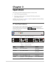


Chapter 3 Operation Vmux-2100 Installation and Operation Manual
3-2 Operating Vmux-2100
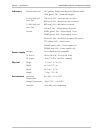
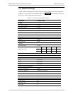
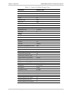
Table 3-1. Vmux-2100 LEDs (Cont.)
Name Function Location
LINK (green)
ON – Good link integrity Ethernet main link
connector
ACT (yellow)
Blinks according to the Ethernet traffic Ethernet main link
connector
LOC (red)
ON – Local sync loss occurred E1 main link and voice
port connector
REM (red)
ON – Remote sync loss occurred E1 main link and voice
port connector
RED (red)
ON – Red alarm is received T1 main link and voice
port connector
YEL (yellow)
ON – Yellow alarm is received T1 main link and voice
port connector
3.2 Operating Vmux-2100
Turning On Vmux-2100
To turn on Vmux-2100:
• Connect the power cord(s) to the mains.
The PWR1(2) indicator lights up and remains lit as long as Vmux-2100
receives power.
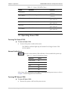
Normal Indications
Table 3-2 shows the correct status of the indicators a few seconds after power-up.
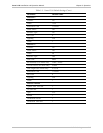
Table 3-2. Vmux-2100 Indicator Status
Indicator Status
PWR1/PWR2 On
TEST Off
ALM On
L Off
R Off
If the above LED indications do not appear following initial power turn-on, refer to
Chapter 5 for the diagnostic test instructions.
Turning Off Vmux-2100
To turn off Vmux-2100:
• Remove the power cord from the power source.