


Preparing for the Control Session 4-1
Chapter 4
Management from a
Terminal
The configuration of Vmux-2100 is performed via menu-driven embedded
software, using a standard ASCII terminal or a PC running a terminal emulation
application connected to the rear panel CONTROL port. Alternatively, you can
configure Vmux-2100 via Telnet connection, which also establishes an inband
management link to the remote unit.
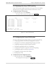
4.1 Preparing for the Control Session
This section describes how to prepare Vmux-2100 and the supervisory terminal for
the control session.
Control Port Interface Characteristics
Vmux-2100 includes a V.24/RS-232 asynchronous DCE port, designated
CONTROL and terminated in a 9-pin D-type female connector. The control port
continuously monitors the incoming data stream and immediately responds to any
input string received through this port.
The terminal can be connected either directly to the Vmux-2100 control port, or
through a modem or any other type of full-duplex data link.
• Direct connection to terminals. Since terminals usually have DTE interfaces,
the connection to the port is made by means of a straight cable.
• Connection through a modem or data link. In this case, you need a cross cable
(RAD’s CBL-VMUX-MM-MODEM) to connect to the CONTROL connector
(see Appendix A for the cross cable wiring diagram).
Preparing the Terminal
Any standard ASCII terminal (a “dumb” terminal or a personal computer running
a terminal emulation application) equipped with a V.24/RS-232 communication
interface can be used to configure Vmux-2100. Appendix A details the pin
assignment and control signal directions of the Vmux-2100 control connector.
Data Terminal Ready (DTR)
When connected and turned on, the terminal sets the DTR line ON (active) to gain
control over Vmux-2100 and starts a configuration or monitoring session.