


Appendix A Interface Connector Specifications Vmux-2100 Installation and Operation Manual
A-2 CBL-VMUX-MM-MODEM Cross Cable
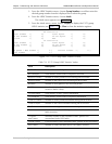
A.3 CONTROL Connector
The control terminal interface terminates in a V.24/RS-232 9-pin D-type female
DCE connector. Table A-3 lists the CONTROL connector pin assignments.
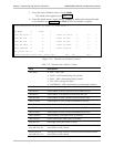
Table A-3. CONTROL Connector Pinout
Pin Function Direction
1 Data Carrier Detect (DCD) Out
2 Receive Data (RD) In
3 Transmit Data (TD) Out
4 Data Terminal Ready (DTR) In
5 Ground (GND) –
6 Data Set Ready (DSR) Out
7 Request To Send (RTS) In
8 Clear To Send (CTS) Out
9 NC –
When connected and turned on, the terminal sets the DTR line ON (active) to gain
control over Vmux-2100 and starts a configuration or monitoring session.
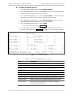
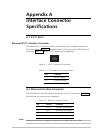
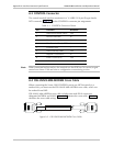
A.4 CBL-VMUX-MM-MODEM Cross Cable
When connecting the Vmux-2100 CONTROL port to an ASCII terminal via a
modem link, you must use the CBL-VMUX-MM-MODEM cross cable, which can
be ordered from RAD.
CBL-VMUX-MM-MODEM cross cable includes two male DB-9 connectors,
designated MODEM and VMUX. Figure A-2 illustrates the cross cable. Table A-4
describes the cross cable wiring.
MODEM
VMUX
CBL-VMUX-MM-MODEM
Figure A-2. CBL-VMUX-MM-MODEM Cross Cable
Note