


Chapter 4 Management from a Terminal Vmux-2100 Installation and Operation Manual
4-18 Configuring Main Link and Voice E1/T1 Ports
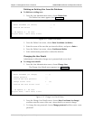
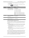
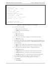
3. From the Main Board menu, select one of the following module types:
M-IP – 10/100BaseT port only
M-IPE1 – 10/100BaseT port and E1 port
M-IPT1 – 10/100BaseT port and T1 port.
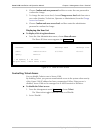
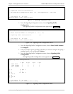
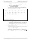
4. From the Hub menu, choose Slot 1 to select the slot 1 module.
The Slot 1 menu appears.
5. From the Slot 1 menu, select one of the following module types:
NO CARD – No module installed in slot 1
V-2E1 – Two E1 ports
V-4E1 – Four E1 ports
V-2T1 – Two T1 ports
V-4T1 – Four T1 ports.
6. Repeat step 4 and step 5 to select the module types for all utilized Vmux-2100
slots.
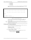
4.7 Configuring Main Link and Voice E1/T1 Ports
Once the main link and voice E1/T1 modules are installed in Vmux-2100 and
identified by the system, you can start configuring the E1/T1 and Ethernet
connections of the unit.
It is recommended to configure the main link and voice (external) E1/T1 ports in
the following order:
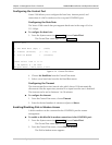
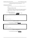
1. Configure the main link:
Set the Ethernet parameters of the main link 10/100BaseT port, if necessary
(autonegotiation or LAN mode).
Configure the E1/T1 parameters of the main link, if necessary (framing
mode, restoration time, clock source, interface type, idle code).
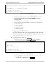
Assign the E1/T1 main link timeslots to carry user data.
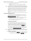
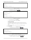
2. Configure external E1/T1 at a group (two E1/T1 ports of the same module)
level:
Assign IP address to a group.
Add bundles to a group (up to five bundles per group)
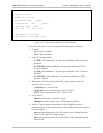
Configure each bundle (frame size, destination IP, destination bundle,
packetizing interval, TOS parameters, compression method, fax relay,
VLAN parameters).
3. Configure external E1/T1 at a single E1/T1 level:
Configure each E1/T1 port at the physical level (framing mode, restoration
time, clock source, interface type, idle code, signaling type, signaling
profile).