


Conversion Instructions
Issue 1 June 2000
2-27
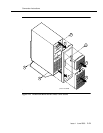
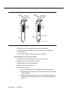
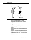
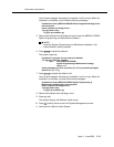
Figure 2-18. GP Synch and DCIU Circuit Card Faceplates
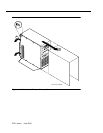
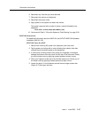
2. Remove the circuit card retaining screw from the faceplate.
3. If a metal slot cover is available, insert the slot cover and replace the
retaining screw.
4. Continue with “MAP/100: Replace the Covers and Cables”.
MAP/100: Replace the Covers and Cables
1. Check all the cable dressing (routing) and connections.
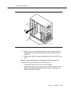
2. Close the Card Cage door.
3. Tighten the eight 1/4-turn fasteners around the card cage access door
(Figure 2-17).
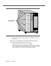
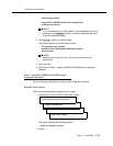
4. For the side covers: Align the holes on the back of the cover with the pegs
on the MAP/100. Push the cover on by applying inward pressure at each
of the corners.
5. For the top cover: Align the holes on the bottom of the cover with the pegs
on the MAP/100. Push the cover on by applying downward pressure at
each of the corners.
6. Reconnect any lines that you have removed. Reconnect the monitor and
keyboard.
7. Reconnect the power cords.
8. Apply power to the system and watch the monitor.
RS-232C
25-pin
connector
RS-232C
25-pin
connector
LED (green)
GP Synch
circuit card
DCIU (EICON)
circuit card
fpin2cd2 KLC 052898