


2-24 Issue 1 June 2000
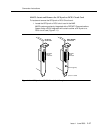
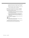
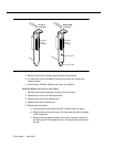
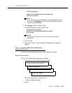
Figure 2-16. GP Synch and DCIU Circuit Card Faceplates
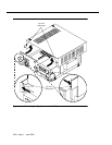
2. Remove the circuit card retaining screw from the faceplate.
3. If a metal slot cover is available, insert the slot cover and replace the
retaining screw.
4. Continue with “MAP/40: Replace the Cover and Cables”.
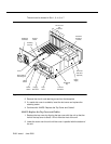
MAP/40: Replace the Cover and Cables
1. Recheck all the cable dressing (routing) and connections.
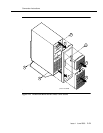
2. Replace the circuit card retaining bracket.
3. Replace the circuit card access panel.
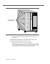
4. Replace the exterior dress cover.
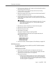
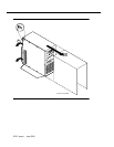
5. Replace the front bezel:
a. Place the bezel frame onto the MAP. It should snap into place.
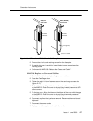
b. Replace the fan filter and cover. The narrow tab should be inserted
in the bottom slot.
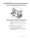
c. Replace the top tape and floppy drive cover, located at the top of
the front panel, if the system has one. The narrow tab should be at
the top.
RS-232C
25-pin
connector
RS-232C
25-pin
connector
LED (green)
GP Synch
circuit card
DCIU (EICON)
circuit card
fpin2cd2 KLC 052898