


2-18 Issue 1 June 2000
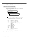
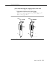
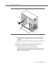
The card can be located in Slot 1, 3, 4, 6, or 7.
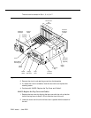
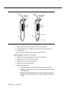
Figure 2-12. MAP/5 Slot Locations
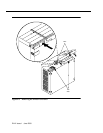
2. Remove the circuit card retaining screw from the faceplate.
3. If a metal slot cover is available, insert the slot cover and replace the
retaining screw.
4. Continue with “MAP/5: Replace the Top Cover and Cables”.
MAP/5: Replace the Top Cover and Cables
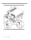
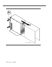
1. Replace the top cover by aligning the top cover with the unit so that the
front of the top cover is about 1/2-inch from the front of the unit.
2. Lower the cover over the unit until the cover is parallel with the bottom of
the unit.
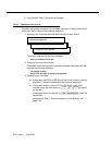
Auxilliary
housing
Keyboard
connector
Lock
Reset
button
Power
switch
Floppy
disk drive
1st hard
disk drive
Tap e
drive
Peripheral
bay
Power
supply
2nd drive
mounting
bracket
2nd hard
disk drive
(optional)
Reset switch
mounting tab
System
board
Circuit card
slot
locations
1
2
3
4
5
6
7
8