


Conversion Instructions
Issue 1 June 2000
2-13
Task 7 - Remove Hardware for the Previous
Integration
If the system has a GP Synch or DCIU circuit card, remove it.
■ For MAP/5 systems, start on page 2-13.
■ For MAP/40 systems, start on page 2-19.
■ For MAP/100 systems, start on page 2-25.
MAP/5 Instructions
For additional information about the MAP/5, see INTUITY MAP/5 Hardware
Installation, 585-310-146.
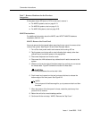
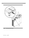
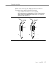
MAP/5: Remove the Front Panel
You must remove the front panel before removing the top cover for access to the
inside of the system. See Figure 2-9 and follow the steps below:
1. Turn off the front power switch and remove the incoming AC line.
2. Tag the power cord plugs with a note indicating that nobody other than
yourself should reconnect power to this equipment.
3. Disconnect keyboard and monitor cords.
4. Disconnect the LAN cable and any cables that will restrict access to the
system.
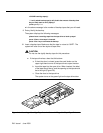
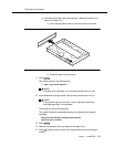
5. Slide the unit over the edge of the table toward you so that you can access
the release tabs. Figure 2-9 shows the location of these tabs.
!
CAUTION:
Do not unbalance the unit so that it falls.
6. Push inward and upward on the two front panel latches to release the
bottom edge of the front panel. See Figure 2-9.
NOTE:
The front panel is flexible enough for you to press one latch and then
the other.
7. When the bottom of the front panel is loose, rotate the panel away from
you and lift it to remove.
8. Return the unit to its correct desktop position.
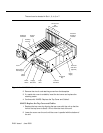
9. Continue with the next step, “MAP/5: Remove the Top Cover”.