


2-20 Issue 1 June 2000
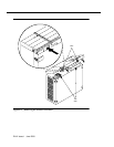
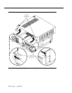
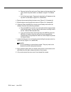
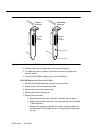
b. Remove the fan filter and cover. Press down on the top edge of the
cover, below the power switch, to release it (Figure 2-13, labeled
#2).
c. Pull off the bezel panel. The panel is attached by 2 fasteners at the
top and 2 at the bottom (Figure 2-13, labeled #3).
4. Remove the screws holding the dress cover (Figure 2-13, labeled #4).
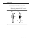
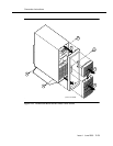
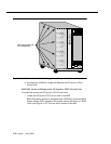
5. Slide the dress cover forward and remove it (Figure 2-14, labeled #5).
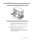
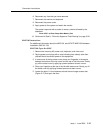
6. (Optional) Place the MAP/40 on its side to more easily work within the
chassis. Use one of the following methods:
a. Place the MAP/40 on its side on a work table with the support base
over the table edge. You may need to disconnect incoming lines to
do this. Label all disconnected lines.
b. If you cannot disconnect incoming lines to the MAP/40, place the
MAP/40 on its side on the floor and rest the end opposite the
support base on large telephone books or similar objects to protect
the support base.
7. Loosen the flat-head 1/4 inch length screws holding the access cover by
two turns only (Figure 2-14, labeled #6).
NOTE:
It is not necessary to remove these screws. They only need to be
loosened to provide adequate clearance.
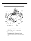
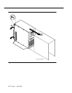
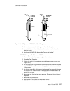
8. Apply pressure gently with your hands, palms down on the access cover
and slide the cover back, towards the rear of the chassis.
9. Lift up and remove the cover once it has cleared the screws.