


System & Station
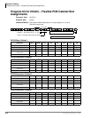
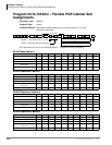
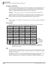
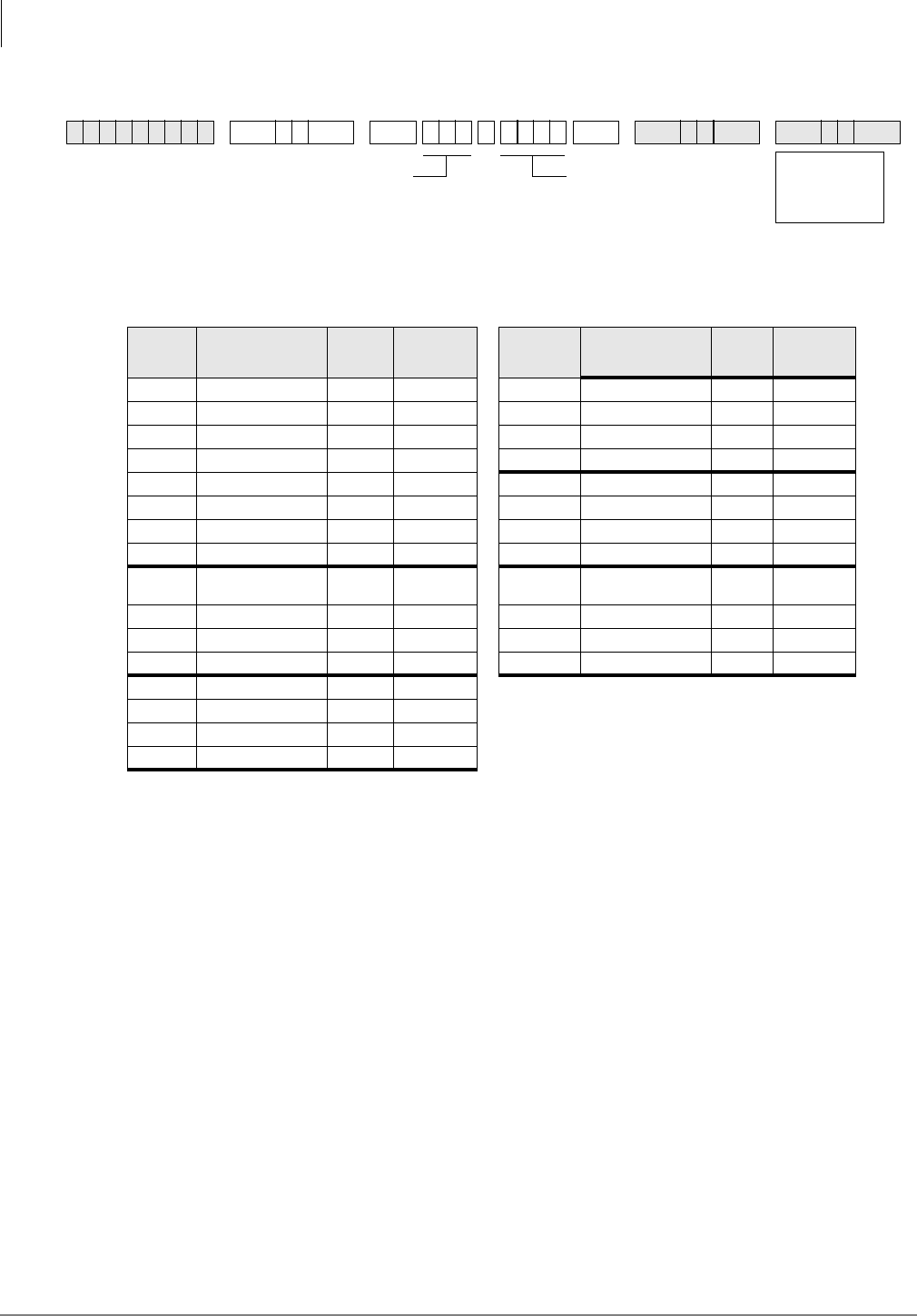
Program 04 – Station Logical Port [PDN] Assignment
3-14 Strata DK Programming 5/00
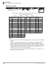
DK40i Record Sheet
Refer to Chapter 2 – DK40i Configuration before installing PCBs in slots 15~18.
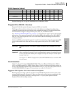
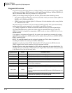
Notes
● Expansion slots 15~18: See DK40i Configuration tables in Chapter 2 of the Strata DK I&M
Manual.
● If KSTU2 is installed in the Base Cabinet, it uses ports 008~012 unless TBSU or TBUU
circuits are installed and configured as station circuits in Program *60. KSTU2 ports are
shifted to start at Port 010 or 012, depending on TBSU or TBUU configuration. If TBUS or
TBUU is installed in the Base Cabinet, each circuit will use two ports, starting with Port 008,
only if the circuit is configured as a station circuit in Program *60. If the BRI circuit is
configured as a line circuit, it does not use station ports.
● Line circuit PCBs (ground, loop, E&M Tie, DID, T1, PRI, BRI) do not use station ports in
DK40i Base or Expansion Cabinets.
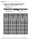
✱ ✱ ✱ ✱ 6SNU +ROG 6SNU +ROG 6SNU +ROG 6SNU +ROG
Expansion Slot Configuration Record:
Slot 15 _______ Slot 16 _______ Slot 17 _______ Slot 18 _______
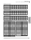
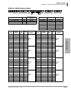
Physical
Ports
Modular Jack
Location Record
Logical
Ports
[PDNs]
Physical
Ports
Modular Jack
Location Record
Logical
Ports
[PDNs]
000 000 016 016
001 001 017 017
002 002 018 018
003 003 019 019
004 004 020 020
005 005 021 021
006 006 022 022
007 007 023 023
008 (see
Notes)
008 024 024
009 009 025 025
010 010 026 026
011 011 027 027
012 012
013 013
014 014
015 015
SELECT = Station Logical Port Number(s)
(see table below)
[PDN] (1~4 digits)
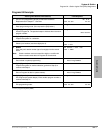
Logical
Ports
(Initialized)