


System & Station
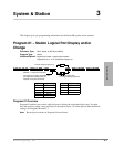
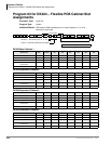
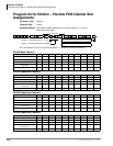
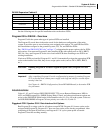
Program 03 for DK40i – Flexible PCB Slot Assignments
Strata DK Programming 5/00 3-5
System & Station
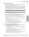
Program 03 for DK40i - Overview
Program 03 tells the system what type of optional PCBs are installed in the Expansion KSU. You
must run Program 03 after installing PCBs with options such as OCA, DIU, etc. Also, run Program
03 for each PCB slot when installing a PCB in that location.
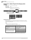
It is not necessary to run Program 03 for slots 00~14. The DK40i automatically assigns the Base
KSU PCBs if they are installed when system power is turned On. However, if DSS is required on
the Base KSU’s DKT circuit 8, you must run Program 03 to assign code 64 to slot 11. If universal
PCBs are installed, Program 91-1 and 91-9 automatically assign the appropriate PCB codes to the
installed slots. But, Programs 91-1 or 91-9 do not assign option codes (such as OCA, DIU, etc.).
Codes allowed in DK40i Expansion KSU: 11, 13, 16, 21~28, 31, 41, 61~62, 64~66, 77, 78, 91, 92 and 81.
CAUTION! Running Program 91-9 erases Program 03 option codes; Program 91-1 does
not.
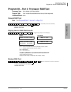
Important! After completing Program 03 set the configuration in memory by running Off and
wait five seconds before turning it back On.
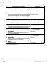
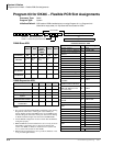
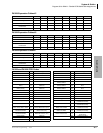
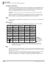
Program 03 is the main record sheet for the hardware configuration of the entire system. It
provides space to record station ports assigned to the station, and numbers assigned to the ground
loop start, CO, Tie, and DID line PCBs. Use the PCB Code Reference Table on the Program 03
record sheet to determine the proper option code for each PCB with an option.
The DK40i Base KSU is divided into four fixed slots, even through the unit has no slots per se.
♦ Slot 00 represents the system’s common control (TMAU2) and optional K4RCU3, K5RCU, or
K5RCU2
♦ Slot 11 contains the KSU’s eight digital circuits/ports (DKU)
♦ Slot 12 contains the KSU’s four optional CO or DID line circuits (TCOU or TDDU) or two
BRI (TBSU or TBUU) circuits
♦ Slot 13 contains the four optional standard telephone circuits KSTU2
♦ Slot 14 contains four optional Caller ID circuits for TCOU (TCIU2)
♦ Slots 15 or 17 support the RDTU (T1) and RPTU (PRI) cards. If one of these PCBs is installed
in slot 15, slot 16 can be used. If installed in slot 17, slot 18 cannot be used.
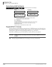
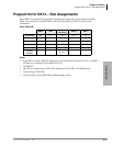
DK40i Slots 15~18 (Expansion KSU Assignment Criteria)
♦ Allowed PCBs: PDKU, RDSU/RSTS, RSTU, RSTU2, PSTU, PEKU, PESU, KCDU,
PRBSU/RBSS, RBUU/RBUS, RCOU/RCOS, RGLU2, RCIU2/RCIS, RWIU, PCOU, RDDU,
REMU, PEMU, PIOU, PIOUS, RSSU, PEPU, Stratagy DK.
Note Some PCBs cannot be installed in slot 18 (see Chapter 2 – DK40i Configuration of the
Strata DK I&M Manual).
♦ Expansion KSU PCBs must be installed in the slots specified in Tables 2-9~2-15, beginning
on or the system may not operate properly.
♦ Slots 15 and 16 support Speaker OCA and RPCI/DIU Data Switching; slots 17 and 18 do not.
All slots support Handset OCA and RPCI-DI TAPI operation.
♦ On DK40i, RCIU2 must be installed in slot 17; RCIU1 cannot be used.
♦ The RWIU must be installed in slot 15 and slot 16 must be vacant to support 9 to 16 wireless
handsets. It can be installed in any expansion slot to support 1~8 wireless handsets.
♦ If the RWIU supports 9 to 16 handsets, program code 61 in slot 15 and 16.