


System & Station
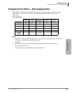
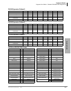
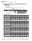
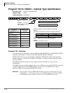
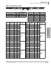
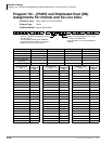
Program 03 for DK424i – Flexible PCB Cabinet Slot Assignments
Strata DK Programming 5/00 3-11
System & Station
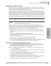
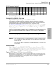
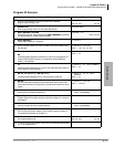
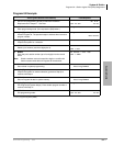
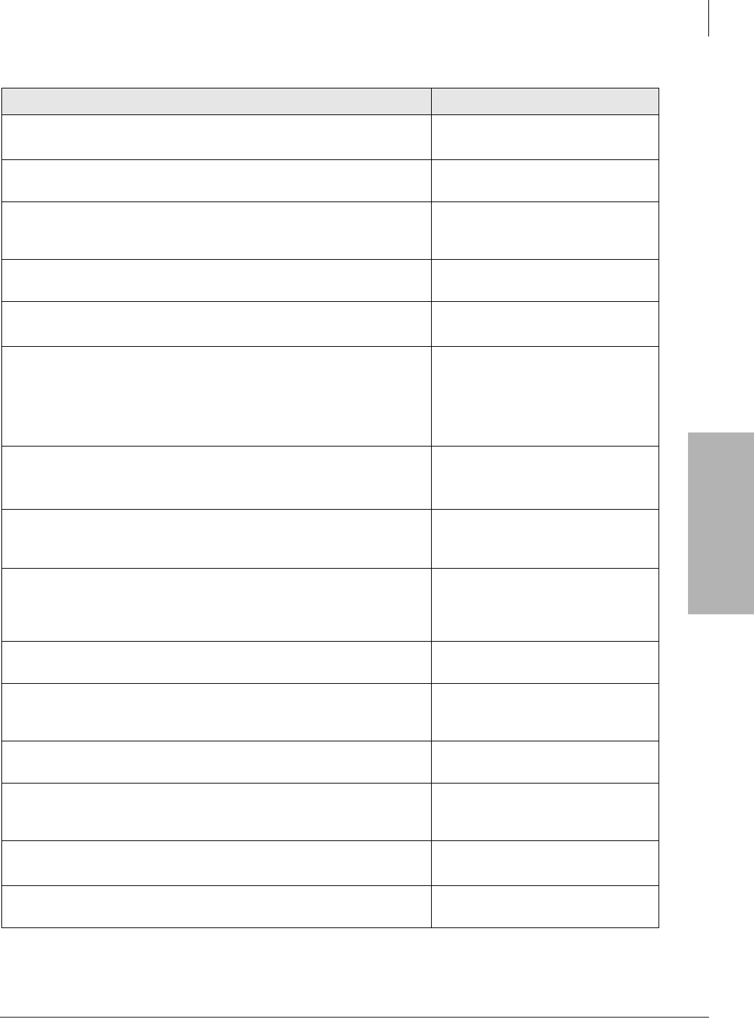
Program 03 Example
Action (press buttons + LED buttons) LCD Response
1. Use an LCD programming phone per Minimum Hardware
Requirements on Page 1-14.
No. 205
Jan 20 Sun 06:43
2. ✱✱✱✱
Enter programming mode. (Do not press [DN] button.)
Program Mode
3. 6SNU6SHDNHU+ROG
Access Program 03. System beeps after 6SNU6SHDNHU is pressed
to indicate program number may be entered.
Program = 03
Data Store
4. 6SNU6SHDNHU
Prepare the system for a selection.
03 Select =
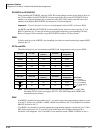
5. Dial a PCB slot number (00~78 for DK424 or 00-18 for DK40i) using
the dial pad.
03 Select = (00~78)
Card = (91, 62 or 00)
The system defaults as follows:
Initialized default assigns slot 00 and 01 to be a non-optioned RCTU
without RRCS DTMF receivers, or DK40i Base without K4RCU3,
K5RCU, and K5RCU2.
03 Select = 00 (Slot Number)
Card = 91
Initialized default assigns slot 11 to be a non-optioned PDKU without
DSS console or OCA (Code 61).
03 Select = 11 (Slot Number)
Card = 61
a (DK424), a (DK40i)
Initialized default assigns slot 12~78 to be empty (Code 00).
03 Select = 12~78 (Slot
Number)
Card = 00
6. a
Dial the PCB code recorded on the record sheet. Refer to the PCB
code reference table on Program 03 record sheet for a definition of the
codes.
03 Select = (00~78)
Card = (00~97)
7. +ROG
Secure data in system programming.
03 Select = (00~78)
Data Programmed
8. 6SNU6SHDNHU
Prepare system for another selection (go back to Step 5) or continue
with Step 9.
03 Select =
9. +ROG
Secure Program 92 data in system memory.
92 Select = ##
Data Programmed
10. 6SNU6SHDNHU
Exit Program 92 (system beeps). Enter another program number or
exit programming mode (go to Step 11).
Program =
11. +ROG
Exit programming mode.
No. 205
Jan 20 Sun 06:58
12. To secure Program 03 entries, Power off for five seconds, then power
on, or run Program 91-2.