Overview
First-time Programming
1-14 Strata DK Programming 5/00
First-time Programming
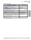
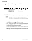
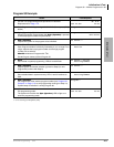
Follow these general procedures the first time you install a system or after major hardware changes
and/or you need to start from scratch.
Step 1: Check Minimum Hardware Requirements
A system must have the following minimum hardware installed for programming, as described in
the Installation chapters of the Strata DK Installation and Maintenance Manual.
➤ To check hardware requirements on the DK14 and DK40i
1. Make sure the base cabinet power supply was tested and is functional.
2. Make sure a 20-button digital LCD DKT telephone (equipped with a programming template)
is connected to any digital telephone circuit (Base KSU, PDKU, QCDU, KCDU or RDSU
digital port); or make sure that a 20-button electronic LCD EKT telephone is connected to a
PEKU electronic port (not PESU).
♦ DK14 and DK40i: make sure the Base KSU’s BATT jumper is in the On position.
➤ To check hardware requirements on the DK424 and DK424i
1. Make sure the base cabinet power supply was tested and is functional.
2. If using an RCTUE/F, remove the small jumper PCB (MBJU) from the front side of the
DK424 base unit backplane (between slot R11 and the RCTU slot. All other RCTUs require
the MBJU PCB. This does not apply to DK424i.
3. Make sure an that the BATT jumper is in the On position for all processors.
4. Make sure a PDKU or PEKU, is installed in the first slot of the in the base cabinet (S11 or
S101) if RSIU is not installed, or if RSIU is installed in S12 or S102).
5. Make sure a 20-button LCD DKT or EKT telephone (equipped with programming template) is
connected to physical port 005 and/or port 013 (PDKU or PEKU - circuit 6/slot 11or 101 and/
or circuit 6/slot 12 or 102). Do not use RDSU or PESU in the programming telephone slot.
Step 2: Initialize the System
1. From a 20-button LCD programming telephone, or from DKi Admin on a PC, run Program
91–9 twice in succession to initialize the system. At this point it is not necessary that all PCBs
are installed. However, if they are, Program 03 codes are automatically assigned to the
appropriate slots.
CAUTION! If you run Program 91-9 while the system is in service, all program data is
erased and all calls are dropped.
Program 91-9 sets the following elements to initial default status:
♦ Data for Programs 00~*99
♦ Speed Dial Memory
♦ Logical/Physical Port Locations
♦ Voice Mail Identification Codes
♦ Character Message Memory


