


System & Station
Program 20 – Computer and Data Interface Unit Configuration
3-58 Strata DK Programming 5/00
Program 20 – Computer and Data Interface Unit
Configuration
Processor Type: DK14, DK40i, all RCTUs and BCUs
Program Type: Station
Initialized Default: LED 17 On, all others Off
Program 20 Overview
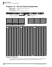
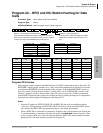
Program 20 identifies the digital station ports connected to RPCI/PDIU and the type of PDIU
connected.
RPCIs have two modes: the Data Switching (DIU mode) and the Application Program Interface
(or TAPI) mode. In the DIU mode, the RPCI operates as a PDIU-DI (Integrated Data Interface
Unit); all Program 20 options apply except LED 10 and LED 11 - which only apply to the RPCI in
TAPI mode. In TAPI mode the RPCI does not require Program 20 assignments, except for LED 10
and/or LED 11 if ANI, DNIS, and/or Caller ID must be sent from the RPCI-DI to the PC to which
it is connected.
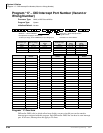
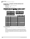
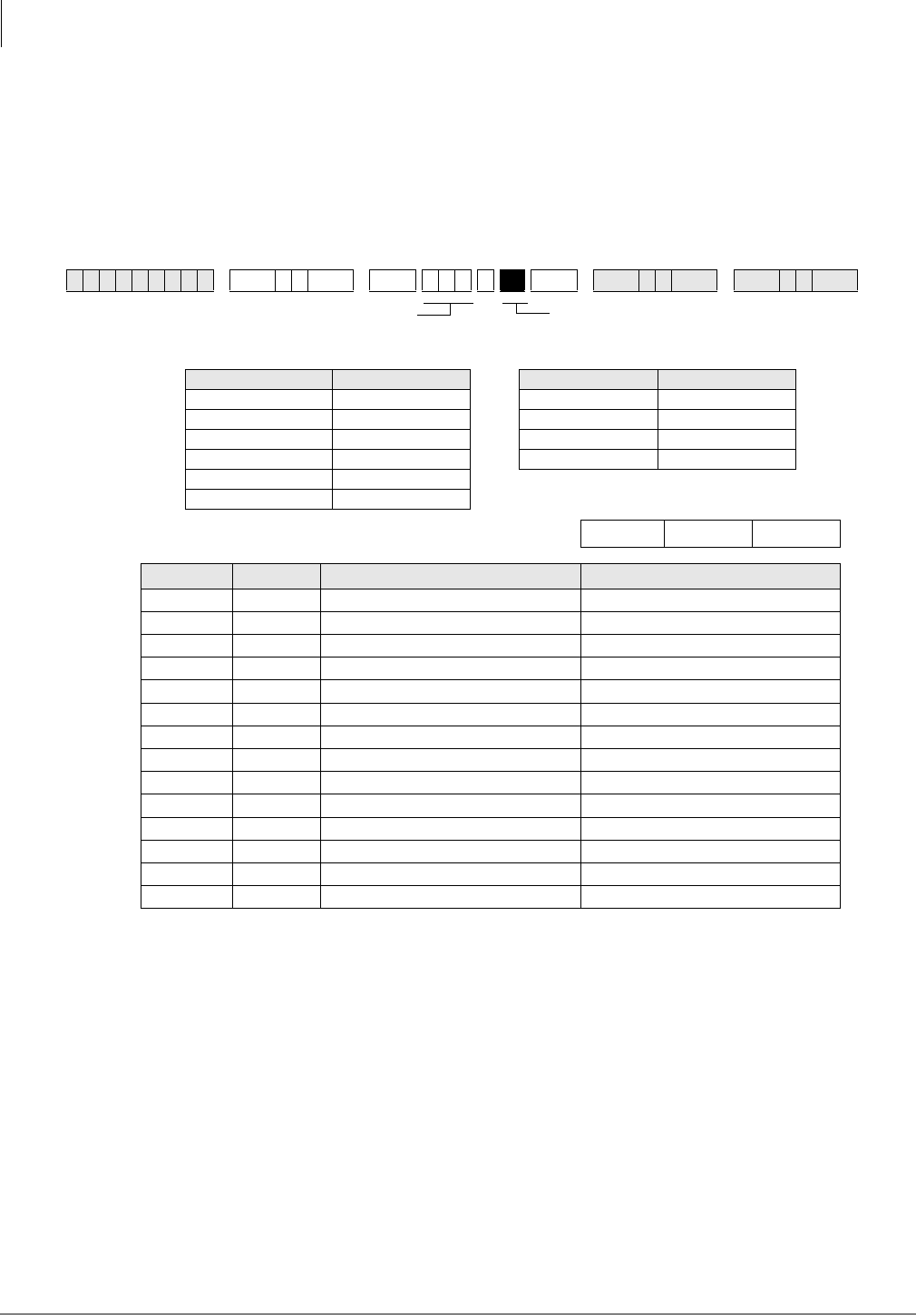
✱ ✱ ✱ ✱ 6SNU +ROG 6SNU +ROG 6SNU +ROG 6SNU +ROG
Processor Type Port Range Processor Type Port Range
DK14 000~009 B1CU 000~055
DK40i 000~027 B2CAU/BU 000~111
RCTUA 000~031 B3CAU/BU 000~191
RCTUBA/BB 000~079 B5CAU/BU 000~335
RCTUC/D 000~239
RCTUE/F 000~335
DK40i Base, PDKU, RDSU, KCDU Digital Port Number
LED X LED On LED Off
20 Data Security Group 4 Not Included
19 Data Security Group 2 Not Included
18 Data Security Group 3 Not Included
17 Data Security Group 1 Not Included
12~16 Not Used
11 RPCI-DI DNIS Sent RPCI-DI DNIS Not Sent
10 RPCI-DI Caller ID/ANI Sent RPCI-DI Caller ID/ANI Not Sent
07~09 Not Used
06 DTR Pulse
with Data Release No DTR Pulse
05 Auto Pause Behind PBX No Auto Pause
04 PDIU-DS Connected PDIU-DI/RPCI-DI Connected
03 PDIU-DS to Modem Connection PDIU-DS to other type DCE or DTE
02 AT Commands and Result Codes AT Commands Only
01 PDIU-DS or RPCI Connected No PDIU-DS or RPCI Connected
SELECT = PDKU/PDSU Station Logical Port
Number that is connected to PDIIU-DS or to
DKT with PDIU-DI or RPCI-DI
LED Buttons 01~06 define data port type;
LED Buttons 17~20 assign data port to
security group.