


System & Station
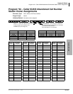
Program *50 – Caller ID Circuit Assignments to CO Line PCBs
Strata DK Programming 5/00 3-131
System & Station
Program *50 – Caller ID Circuit Assignments to CO
Line PCBs
Processor Type: DK14, DK40i, all RCTUs and BCUs
Program Type: System
Initialized Default: No RCIU/RCIS circuits assigned
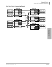
Note The Tip/Ring leads of RGLU, RCOU, RCOS, and PCOU Caller ID CO lines assigned to
RCIU2/RCIS circuits must be bridged at the MDF. The Tip/Ring leads of TCOU and
TCIU2 are bridged by the PCB connectors in the DK40i Base KSU.
For more information on RCIU/RCIS assignments and installation, refer to Chapter 7 –
Universal Slot PCB Installation and Chapter 8 – Universal Slot PCB Wiring Diagrams in
the Strata DK I&M Manual.
On DK14, the Tip/Ring leads of the CO line circuit must be connected to the line Tip/Ring
leads of the Caller ID interface box. (See Chapter 1 – DK14 Installation, Figure 1-18 and
the Caller ID text under “WSIU1 Serial Interface Board” in the Strata DK I&M Manual.)
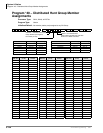
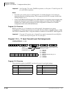
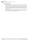
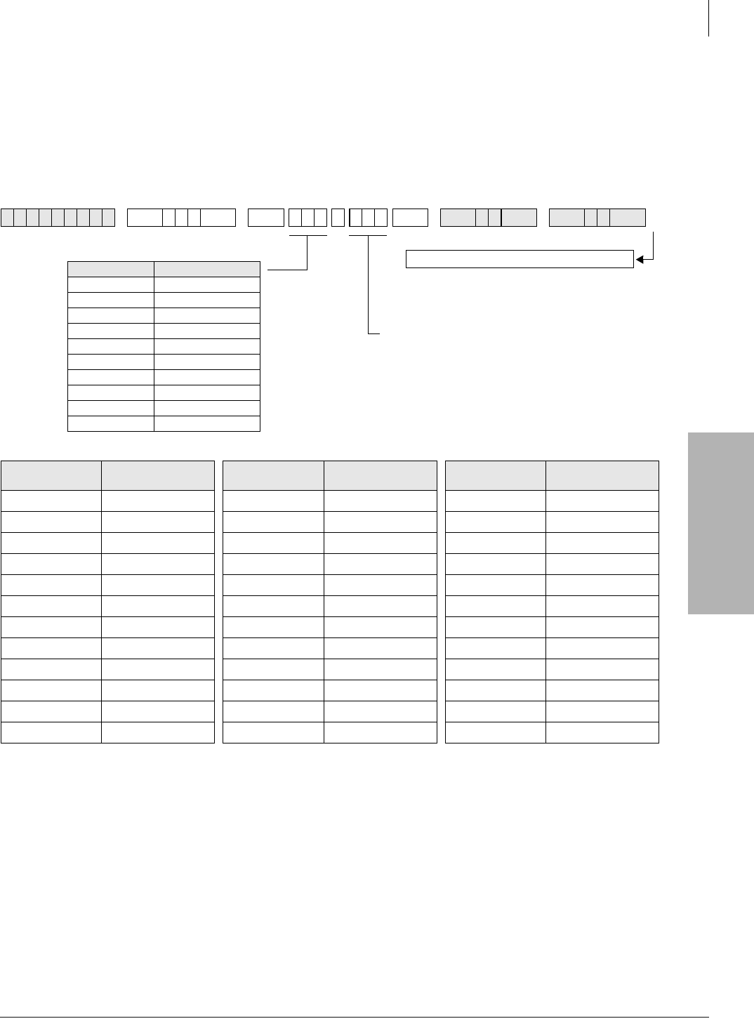
✱ ✱ ✱ ✱6SNU✱ +ROG 6SNU +ROG 6SNU +ROG 6SNU +ROG
CO Line Number
RCIU/RCIS Circuit
Number Assigned
CO Line Number
RCIU/RCIS Circuit
Number Assigned
CO Line Number
RCIU/RCIS Circuit
Number Assigned
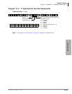
System power must be cycled or Program 91-2 must
be run after completing *50 data entry to transfer
data from temporary memory to working memory.
CIUNO = RCIU/RCISU Caller ID circuit number
(001~200) or use LED Button 01 to erase data. For
DK14, enter the Caller ID interface box line number
(001~004).
Any Caller ID circuit can be assigned to any analog
ground or loop start CO line circuit. Circuit numbers
do not have to match.
Processor CO Line Range
DK14 001~004
DK40i 001~012
RCTUA 001~016
RCTUBA/BB 001~048
RCTUC/D 001~144
RCTUE/F 001~200
B1CU 001~032
B2CAU/BU 000~120
B3CAU/BU 000~120
B5CAU/BU 000~200
Run Program 91-2