


132
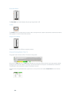
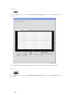
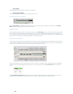
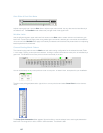
Input Meter
Shows the level of the signal as it enters the compressor.
Compression Meter
Shows the instantaneous compression value at a given time.
Gain Slider & Process Meter
Use the Gain Slider to establish the gain level for this processing channel. Range is -65 to 20dB. The Process
Meter shows the signal level when a signal is present.
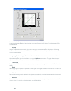
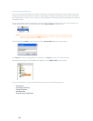
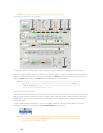
Min/Max Limits
Use the yellow and green upper and lower limit arrows on the Gain Scale to set minimum and maximum gain level
limits. These limits only apply when using relative gain commands; absolute gain commands can exceed the min
and max limits. Min/Max limits apply to all serially connected control devices and prevent users from adjusting levels
beyond the min/max levels, provided relative gain commands are used.
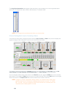
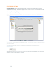
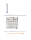
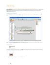
Channel Routing Matrix
The channel routing matrix shows the Matrix row and audio routing configuration for the selected channel (Process
A in this case). Clicking a cross point box selects it, clicking it a second time sets the cross point, as indicated by a
colored box. The dB level for set cross points is shown numerically in the box.
You can click directly on any cross point box to set a cross point, or leave it blank, as required for your installation.
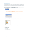
To adjust cross point gain/attenuation, right-click on a cross point box and select Cross Point from the shortcut
menu.
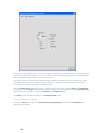
The Cross Point Attenuation slider appears as shown below. Move the slider or use the selector box to set the
gain/attenuation level in dB. The range is from -60 to 12dB in .5dB increments. The default is 0dB.