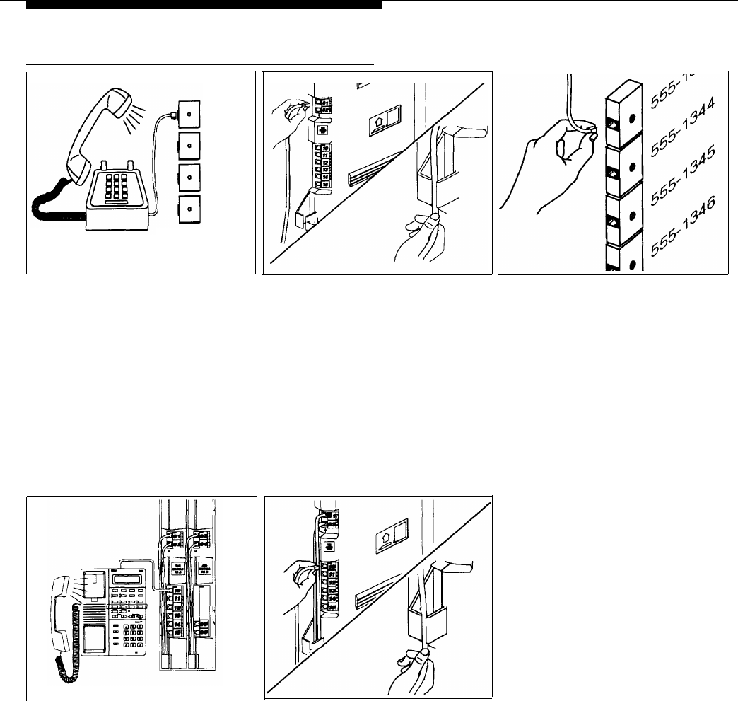
Connecting Lines and Extensions
555-1343
555-1344
555-1345
555-1346
Network
Interface
Jacks
1
Test for dial tone at the network
2
3
interface jacks before connecting
Centrex lines. Connect a standard
A) Connect the telephone line
cords to the line jacks on the 206 and
400 modules, starting with the top line
touch-tone phone to the first network
jack on the leftmost 206 module. B)
interface jack. Lift the handset and
Route each cord through the hook on
listen for dial tone. Repeat for each
the front of the module, then through
network interface jack. (If there is no
the slot between the module and the
dial tone, contact your local telephone
base of the backplane. Leave at least
company before continuing.)
two feet of slack in cords to allow for
easy replacement of modules (see
“Replacing a Module” on page 2-14).
4
Test the lines. Plug an MLS- or
5
A) Connect the modular telephone
MLC-model phone into extension jack
cords to the 206 module extension
10. Press the line buttons for each
jacks, starting at the top jack on the
Centrex line and listen for the dial tone.
leftmost module. B) Route each cord
through the hook on the front of the mod-
ule, then through the slot between the
module and the base of the backplane.
Leave at least two feet of slack in cords
to allow easy replacement of modules
(see “Replacing a Module” on page
2-14). Connect each cord to the appro-
priate wall jack or directly to a phone.
NOTE: If wall jacks are not installed,
call a qualified service technician.
Connect the free end of each
telephone line cord to the appropriate
network interface jack.
2-10
Installing the Hardware


