


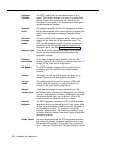
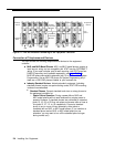
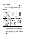
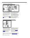
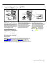
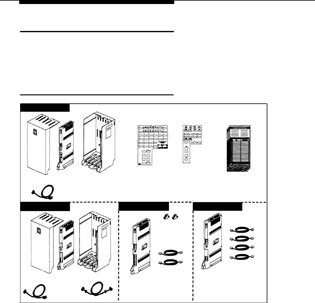
Installation Procedures
Before installing the premises equipment, be sure you read the safety
instructions on page 2-ii. In addition, be sure you have the parts shown in
Figure 2-3 (if not, call the Helpline as instructed on the inside front cover of this
guide). You will have up to four types of component packages; Figure 2-3
shows the contents of each package type in an area marked by a dashed line.
Required Parts
Primary Carrier
Primary
Cover
Processor
Backplane
Module
AC Power Cord
MLS-34D
Programming
Overlay
MLS-12D
Programming
Overlay
Quick Reference Cards
(3 packages of 6)
Expansion Carrier
206 Module
400 Module
267F2
Bridging
Adapters (2)
7-foot
Expansion
7-foot
Processor Module
Backplane
206
Telephone
400
Module
Line Cords (2)
Module
Cord
AC Power
Expansion Cable
Cover
Telephone
Line Cords (4)
Figure 2-3. Premises Equipment Parts
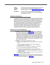
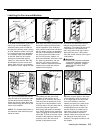
NOTES:
1.
For each carrier, you will need to obtain four #12 screws of the appropriate
type for the wall and the weight of the carrier (a carrier with two 206 modules,
two 400 modules and a processor module weighs approximately 27.5 pounds).
2.
If you need modular telephone cords for connecting the extension jacks on
the equipment controller to the modular connecting blocks for extensions in the
equipment room, short telephone cords for wall mounting MLS-model phones,
or a 355A/355AF adapter and D8W telephone cord for connecting a call
reporting device, order them before installation. See “Product Ordering
Information” in Appendix C for ordering instructions.
2-8
Installing the Equipment