


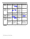

PAGE Jack
■ Draws current on inner wire pair
■ Provides contact closure on outer wire pair
■ 600 ohm impedance
SMDR Jack
■ 1200 baud
■ 8 data bits, 2 stop bits
■ No parity
■ 355A or 355AF adapter required
Environmental
■ Mount on a wall at least 2 feet (0.6 meters) from the floor (wall mounting required)
Requirements—
■ Locate within 5 feet (1.5 meters) of the network interface jacks and an electrical outlet not
Equipment
controlled by a switch, using supplied 7-foot (2.1-meter) cords
Controller
■
Mount the Expansion Carrier at least 6“ and not more than 24” away from the Primary Carrier
■ Operating temperature 32° to +104°F (0° to +40°C), not in direct sunlight
■ Humidity 15%–90%, noncondensing
■ For proper ventilation and easy replacement of modules, provide at least 6” (2.34cm) clearance
at the top and sides, and 2 feet (0.6 meters) at the front and bottom of the control unit.
■ Locate in an area free of excess moisture, corrosive gases, dust, and chemicals
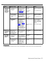
Electrical
■ 10 Watts (35 BTUs/hour) per 400 module, normal and peak power consumption
Specifications
■ 65 Watts (225 BTUs/hour) per 206 module during normal operation
■ 100 Watts (350 BTUs/hour) per 206 module during peak power consumption
■ 4 Amps peak current at full controller capacity (processor modules and four 206 modules)
■ 4-day memory backup (96 hours)
Electrical
■ 90–130 VAC, 50–60 Hz, 3-prong outlet separate ground, separately fused at 15 Amps
Requirements
■ Outlet must not be controlled by an on/off switch
■ Grounding to comply with Underwriters Laboratories (UL) 1459:
A. An insulated rounding conductor that is not smaller in size and equivalent in insulation
material and thickness to the grounded and ungrounded branch circuit supply
conductors, except that it is green with or without one or more yellow stripes, is to be
installed as part of the circuit that supplies the premises equipment.
B. The grounding conductor mentioned in item A is to be connected to ground at the service
equipment.
C. The attachment-plug receptacles in the vicinity of the premises equipment are all to be of
a grounding type, and the grounding conductors serving these receptacles are to be
connected to earth ground at the service equipment.
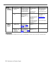
Requirements for
Installation of a telephone or other standard (tip/ring) device in another building requires the
Out-of-Building
following In-Range Out-of-Building (IROB) protectors to protect the controller and device from
Extensions
electrical surges:
■ MLS-model telephone: two AT&T 503A1 or 504A1 protectors
■ Standard device: one AT&T 503A1 or 504A1 protector plus one carbon block protector
Wiring
■ MLS-model phones: AT&T SYSTIMAX™ or at least 2-pair (4-wire) star (“home run” not “loop”)
■ Other standard telecommunications equipment (single-line phones, fax machines, answering
machines, etc.): 1-pair (2-wire) mounting cords (AT&T D2R mounting cords recommended)
■ Bridging adapter: AT&T 267F2
■ Range: 1,000 feet (305 meters) for MLS phones; 3,000 feet (915 meters) for standard devices
Primary
■ 68000 microprocessor, 64K RAM, 256K ROM
Processor
Module
Expansion
■ 12 megahertz, 128K RAM, 64K ROM
Processor
Module
D-2
Specifications