


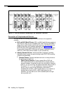

Example Configuration
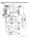
These two pages show an equipment controller with three
206 modules and three 400 modules, giving this particular
configuration a capacity of 16 lines and 18 extensions. Note
that two of the extensions are a Hotline phone and a
doorphone, which do not use primary lines. Although your
configuration may differ, this example shows various
devices connected to 10 of the 18 extensions. The circled
numbers in the figure refer to the following list, which gives
a brief description of the equipment components.
■
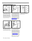
Equipment Controller
The equipment controller in this example contains both the
primary and the expansion carriers, plus these components:
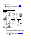
■
Backplanes. The backplanes distribute power to the
premises equipment and connect the modules.
206 Modules. Each 206 module has jacks for two
lines and six extensions.
400 Modules. Each 400 module provides four line
jacks but no extensions. Notice that each 400 module
is installed to the right of a 206 module.
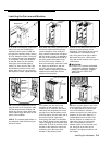
Primary Processor Module. The primary processor
module manages the components connected to the
equipment controller. The following auxiliary
equipment jacks are on the processor module:
■
■
■
■
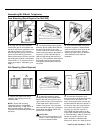
PAGE. A loudspeaker paging system plugs directly
into this modular jack. The premises equipment is
compatible with any AT&T paging system, including
the AT&T PagePac6® Plus shown here.
SMDR. A call accounting device or printer connects
to this jack using an AT&T 355A or 355AF adapter.
AT&T’s 572 serial printer is shown here.
MUSIC ON HOLD. An AT&T Magic on Hold®
system is connected to this jack to provide custom-
ized music and messages for callers on hold. Other
types of audio equipment (including a CD player,
cassette player, or stereo receiver) can be
connected with an audio cord and RCA phono plug.
Expansion Processor Module. The expansion
processor module extends the primary processor
module’s management capabilities to the modules in
the expansion carrier.
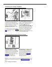
Line Jacks. All four jacks on each 400 module and
the top two jacks on each 206 module connect to
Centrex lines.
Extension Jacks. Inside wiring for telephones and
other telecommunications equipment connects to the
bottom six jacks on each 206 module.
Network Interface Jacks. These jacks provide
access to Centrex lines. Each Centrex line is
connected to the equipment controller by plugging one
end of the telephone Iine cord into one of these jacks,
and the other end into a line jack on a 206 or 400
module.
Expansion Cable. The expansion cable connects the
primary processor module to the expansion processor
module.
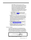
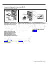
Extensions
This example shows MLS- and MLC-model phones and
industry-standard devices connected to the extension jacks
in the equipment controller by way of the building’s inside
wiring.
Extension Jack 10: These devices are connected:
MLS-34D Display Phone. Typically, the
receptionist on extension 10, called the primary
programming extension, has an MLS-34D phone.
AT&T 267F2 Bridging Adapter. This adapter
permits the connection of two devices—in this
example a standard touch-tone phone and an
MLS-34D phone—on one extension jack. This is
called a combination extension. (You cannot
connect two MLS- or MLC-model phones.)
Standard Phone.
The MLS-34D phone on
extension jack 10 will not work during a power
failure; therefore, the receptionist can use the
standard phone.
Extension Jack 11: MLS-34D Display Phone.
Another MLS-34D is connected to extension jack 11, or
the backup programming extension. You can program
the premises equipment from this extension while the
phone at extension jack 10 is free to handle calls.
NOTE:
An MLS-34D or MLS-12D is required for
programming at extension jack 10 or 11, or both. Use
an MLS-12D only if there are no MLS-34D phones
installed at your site.
Extension Jack 12: Fax Machine and Standard
Phone. A fax machine and standard phone are
connected together on this extension. This setup lets
you share the fax line with a telephone. Alternatively,
you can use an MLS- or MLC-model phone at another
extension to monitor the fax machine (see page 7-2).
Extension Jack 13: MLS-12D Phone and Bell.
A loud
bell, to provide loud ringing in a noisy area, is
combined with an MLS-12 phone.
Extension Jack 14: MLS-12 Phone. This phone is
similar to the MLS-12D telephone (see extension jack
13), but it has no display.
Extension Jack 15: MLS-6 Phone and Answering
Machine. An MLS-6 phone and an answering machine
are connected to this extension. (See page 7-5).
Extension Jack 16: Standard Phone. A standard
touch-tone phone (such as you might have in your
home) is connected to this extension jack.
Extension Jack 17: MLC-6 Cordless Phone. An
AT&T MLC-6 cordless telephone is connected to this
extension. It works like the corded MLS-6.
Note how the Hotline phone and doorphone are connected
to the last available extension jacks on the last installed
206 module in the equipment controller:
Extension Jack 26: Hotline—Standard Phone.
When
the handset of this phone is lifted, another phone rings.
Extension Jack 27: Doorphone. A doorphone is
installed at the building entrance. When someone at
the entrance presses the doorphone button, the
designated extensions (five maximum) in the office
alert.
2-6
Installing the Equipment