


View Cabinet Diagram –––––––––––––––––––––––––––––––––––––––––––––––––––––––––––––––––––––––––––
44
DKAdmin/DKBackup
View Cabinet Diagram
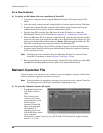
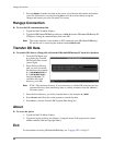
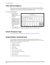
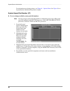
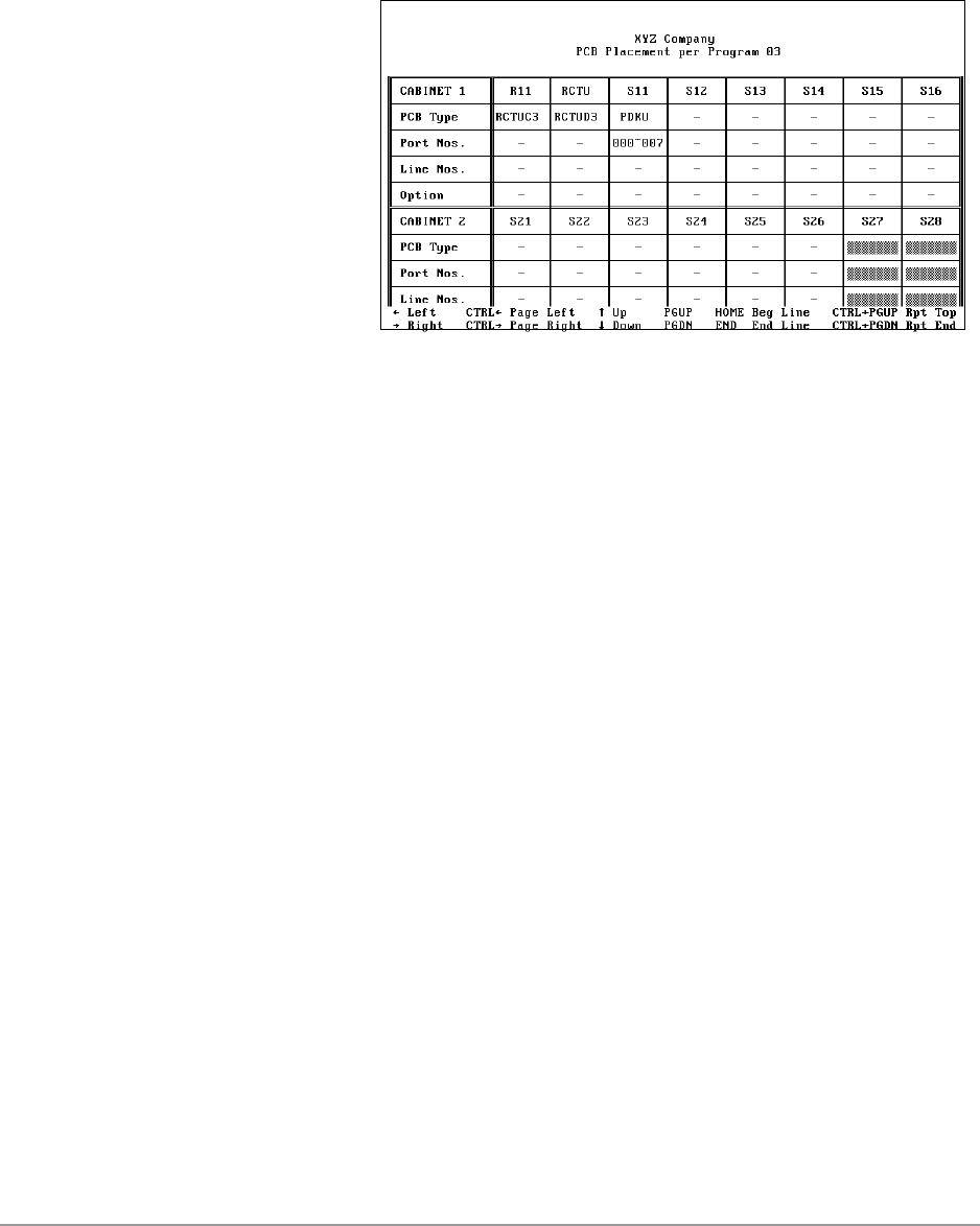
The base and expansion cabinet diagram displays the current Printed Circuit Board (PCB)
configuration for the customer’s Strata DK system. The diagram varies based on the Strata DK
model and processor listed in the Customer File Maintenance screen.
➤ To view cabinet diagram
1. Select a customer
using the Select
Customer option in the
File Menu.
2. From the
Administration Menu/
Backup Menu, press g
or Enter to display
the PCB Placement per
Program 03 screen for
the selected customer
(example shown at
right).
3. Use the left/right
arrow, CTRL, Home, End, Page Up and Page Down keys to scroll the screen.
Check Processor Type
For the Check Processor Type option, see “Check Processor Type” on Page 100.
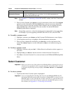
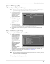
System/Station Administration
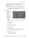
The System/Station Administration option in the Administration Menu enables you to
program or update system ports and stations. Depending on your password level, you can have
complete control over assignments of such items as:
♦ Logical ports assignments
♦ Telephone locations
♦ PDN/Intercom numbers
♦ DID numbers
♦ LCD user names
♦ Voice mail forward ID codes
♦ Voice mail message waiting codes
♦ System speed dials
♦ System messages
♦ Station attributes (40 individual telephone options)