


PDIU-DS Modem Pool Installation ––––––––––––––––––––––––––––––––––––––––––––––––––––––––––––––––––
142
DKAdmin/DKBackup
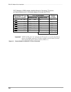
2. PDIU-DS port Program 20 options:
LED 01, 02, 04, and 17 on; all other LEDs off for PDIU-DS port if connecting the modem
to a CO line; if connecting the modem to an RSTU port, turn on LED 01, 02, 03, 04, and
17 for the PDIU-DS port.
Notes
● LED 02 must be turned off until the AT commands shown in 3 below have been set on the
modem connected to the PDIU-DS. After the listed AT commands are sent to the modem,
LED 02 in program should be turned on for the PDIU-DS port.
● Only turn LED 03 on if the telephone/PDIU-DI modem pool key (Program 39-code 455)
is required. Otherwise turn LED 03 off. If LED 03 is OFF, the PDIU-DS READY LED
will indicate the modem carrier detect status; and, the PDIU-DS will beep when a PDIU-
DI connects to it. If LED 03 is ON, the telephone modem key will indicate modem pool
status but the PDIU-DS READY LED will always be off and the PDIU-DS will not beep
when a PDIU-DS connects to it.
3. The following AT command line must be sent to the modem (sent via DK Dialer Modem/
DIU initialization string):
ATS0=1 S2=43 E0 Q0 &C1 &D2 V1 &W0 &Y0 <CR> (See Note 1 above.)
4. If connecting the modem to an RSTU port, use Program 21 to assign the PDIU-DS port to
the RSTU port. Use Program 39 to assign DATA, DATA RELEASE, and MODEM keys to
digital telephones that use the modem pool.
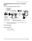
5. Connect the modem “line” to a CO line or RSTU port.
6. Connect the PDIU-DS modular jack to the PDKU port assigned in Program 20.
7. Connect the modem RS-232 connector to the PDIU-DS RS-232 connector with a straight
DB-25 to DB-25 (male to male) cable.
Important! Make sure all PDKU PCBs slots that support PDIU-DS or PDIU-DI are
programmed with Code 62 or 64 in Program 03.
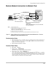
External Maintenance Modem Installation
See Figures 18 and 19, as applicable, and install the external modem in accordance with the
following steps:
Note The Toshiba PPTC RS-232 modular-to-DB25 adapter is factory configured for ASCII
terminal connection. Pins 2 and 3, and Pins 8 and 20 of the adapter must be reversed
on the DB25 end for external modem connection (see wiring diagram below).
1. Connect the modular cord from the RSSU, PIOU or PIOUS TTY port to the PPTC adapter
and then to the external maintenance modem RS-232 25-pin connector.
2. Connect the external maintenance modem line-side to a dedicated CO line, tip and ring
(see Figure 18 on Page 132) or to a dedicated standard telephone port, tip and ring (see
Figure 19 on Page 133). Refer to Chapter 8 – DK16e/DK424 Universal Slot PCB Wiring
in the Strata DK Installation and Maintenance Manual for wiring/interconnecting details.
3. Set the PIOU or PIOUS SW2 switch to match the modem or terminal baud rate:
♦ Push in for 300 bps (baud rate indicator CD4 is lit); let out (by pushing again) for 1200
bps (CD4 is not lit), RSSU is always 1200 bps. Use 1200 bps with DKAdmin/
DKBackup.