


Firmware Pages and Descriptions
72
NXD-700Vi 7" Modero® Wall/Flush Mount Touch Panel with Intercom
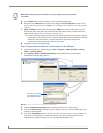
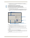
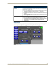
Setup Page
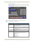
This page (FIG. 53) centers around basic Modero panel properties such as: Connection Status of the panel,
Display Timeout, Inactivity Page Flip Time, Inactivity page file, and the Panel Brightness.
The elements of the Setup page are described in the table below:
FIG. 53 Setup page
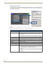
Setup Page Elements
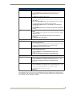
Exit: Returns you to the Main touch panel page. In this case, the previous page is the
default Main page.
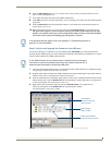
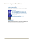
Connection Status icon: This visual display of the connection status allows the user to have a current
update of the panel’s connection status regardless of what page is
currently active.
• A Lock only appears on the icon if the panel has established a connection
with a currently secured target Master (requiring a username and password).
Connection Status: Displays whether the panel is communicating externally, the encryption status
of the communicating Master, what connection type is being used (Ethernet or
USB), and what System the panel is a part of.
This visual display of the connection status is also reflected at the upper-right of
each firmware page. This allows the user to have a current visual update of the
panel’s connection status regardless of what page is currently active.
• When a connection is established, the message displayed is either:
"Connected via Ethernet " or "Connected via USB ".
• If no connection can be established by the Modero panel, it will continue to try
and establish a connection while displaying: "Attempting via ...".
• The word "Encrypted" appears only when an encrypted connection is
established with a target Master.
• The panel must be rebooted before incorporating any panel communication
changes and detecting any active Ethernet connections.
The Ethernet connection is not detected until after a reboot.
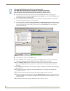
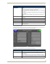
Display Timeout: Sets the length of time the panel can remain idle before activating the sleep
mode. When the device goes into sleep mode, the LCD is powered-down.
• Press the UP/DN buttons to increase/decrease the time until the panel
times out. Range = 0 - 240 minutes.
• Use this button to set the timeout value to zero and disable the sleep mode.
• Note: Display timeout values affect battery performance. Small timeout values
increase the life of the battery charge. Greater timeout values may require
more frequent battery charging.
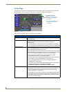
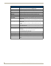
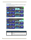
Connection Status
Red Connection Status icon -
Green Connection Status icon -
indicates no connection
indicates communication
to a Master
to a Master