


Upgrading Modero Firmware
68
NXD-700Vi 7" Modero® Wall/Flush Mount Touch Panel with Intercom
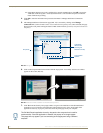
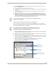
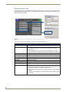
9. Place a checkmark within the Automatically Ping the Master Controller to ensure availability radio box
to make sure the Master is initially responding online before establishing full communication.
10. Click OK to close the current New TCP/IP Settings dialog and return to the previous TCP/IP Settings
dialog where you must locate your new entry within the List of Addresses section.
11. Click the Select button to make that the currently used IP Address communication parameter.
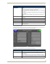
12. Click OK to return to the Communications Settings dialog and place a checkmark within the
Authentication Required radio box if your Master has been previously secured with a username/password.
13. Click on the Authentication Required radio box (if the Master is secured) and then press the User Name
and Password button to open the Master Controller User Name and Password dialog.
14. Within this dialog, you must enter a previously configured username and password (with sufficient rights)
before being able to successfully connect to the Master.
15. Click OK to save your newly entered information and return to the previous Communication Settings
dialog where you must click OK again to begin the communication process to your Master.
16. Click Ye s to interrupt the current communication from the Master and apply the new settings.
17. Click Reboot (from the Tools > Reboot the Master Controller dialog) and wait for the System Master to
reboot. The STATUS and OUTPUT LEDs should begin to alternately blink during the incorporation. Wait
until the STATUS LED is the only LED to blink.
18. Press Done once until the Master Reboot Status field reads *Reboot of System Complete*.
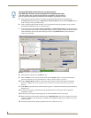
19. Click the OnLine Tree tab in the Workspace window to view the devices on the System.
The default System value is one (1).
20. Right-click the associated System number and select Refresh System. This establishes a new connection
to the specified System and populates the list with devices on that system. The communication method is
then highlighted in green on the bottom of the NetLinx Studio window.
Step 2: Prepare the Panel For Communication Via an IP
1.
Press the blue Type field (from the Master Connection section) until the choice cycles to the word
Ethernet.
2. Press the blue Mode field until the choice cycles to the word URL.
By selecting URL, the System Number field becomes read-only (grey) because the panel pulls this
value directly from the communicating target Master (virtual or not). A Virtual Master system
value can be set within the active AMX software applications such as: NetLinx Studio, TPD4, or
IREdit.
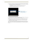
3. Press the red Master IP/URL field to open a Keyboard and enter the NetLinx Master’s IP Address
(obtained from the Diagnostics - Networking Address dialog of the NetLinx Studio application).
4. Click Done to accept the new value and return to the System Configuration page.
5. Do not alter the Master Port Number value (this is the default value used by NetLinx).
6. Press the Back button to return to the Protected Setup page and press the on-screen Reboot button to
restart the panel and save any changes.
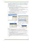
Step 3: Verify and Upgrade the Panel Firmware Via an IP
1.
Click the OnLine Tree tab in the Workspace window to view the devices on the System.
The default System value is one.
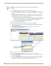
2. Right-click the associated System number (from the Workspace window) and select Refresh System to
detect of all devices on the current system, establish a new connection to the Master, and refresh the
System list with devices on that system.
3. After the Communication Verification dialog window verifies active communication between the PC and
the Master, verify the panel appears in the OnLine Tree tab of the Workspace window (see FIG. 48 on
page 65). The default Modero panel value is 10001.
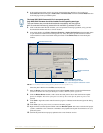
If you are currently connected to the assigned Master, a popup asks whether you
would want to temporarily stop communication to the Master and apply the new
settings.