


Installation
33
NXD-700Vi 7" Modero® Wall/Flush Mount Touch Panel with Intercom
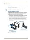
Installing the NXD into a Flat Surface using #4 screws
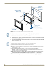
Mounting screws (#4-40, included) are secured through two sets of circular holes located at the left and right
sides of the NXD-700Vi. The most important thing to remember when mounting the NXD Wall Mount is
that the outer frame (Mounting Tabs) must be installed flush against the mounting surface.
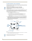
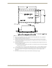
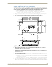
Refer to SP-2258-01 for detailed installation dimensions (reproduced in FIG. 15).
It is recommended that you cutout the surface slightly smaller than what is outlined in the
installation drawings so that you can make any necessary cutout adjustments.
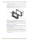
1. Prepare the area by removing any screws or nails from the surface before beginning the cutout process.
2. Cut out the surface for the NXD Wall Mount unit using the dimensions shown in FIG. 15.
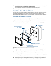
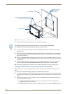
3. Remove the Faceplate/bezel (A in FIG. 16) from the main NXD unit (B in FIG. 16) by gripping the
faceplate and pulling with gentle outward force.
4. Thread the incoming power, RJ-45, Ethernet, USB, and any optional audio/video wiring (from their
terminal sources) through the surface opening. Leave enough slack in the wiring to accommodate any re-
positioning of the panel.
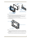
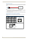
5. Connect all data and power wiring connectors to their corresponding locations along the left side of the
(un-powered) NXD touch panel.
Verify that the terminal end of the power cable is not connected to a power source before plugging
in the 2-pin power connector.
The USB connectors can be from a either a USB extension cable, or a wireless USB RF transmitter.
6. Test the incoming wiring by connecting the panel connections to their terminal locations and applying
power. Verify that the panel is receiving power and functioning properly before finalizing the installation.
FIG. 15 NXD-700Vi Wall Mount panel dimensions using #4-40 mounting screws