


Configuring Communication
56
NXD-700Vi 7" Modero® Wall/Flush Mount Touch Panel with Intercom
Master Connection to a Virtual Master via Ethernet
Before beginning:
1. Verify the panel has been configured to communicate with the Wireless Access Point and verify the signal
strength quality bargraph is On.
2. Launch NetLinx Studio 2.x (default location is Start > Programs > AMX Control Disc > NetLinx
Studio 2 > NetLinx Studio 2).
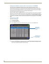
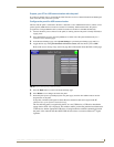
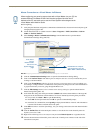
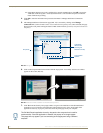
3. Select Settings > Master Communication Settings, from the Main menu to open the Master
Communication Settings dialog (FIG. 40).
4. Click the Communications Settings button to open the Communications Settings dialog.
5. Click on the NetLinx Master radio button (from the Platform Selection section) to indicate that you are
working as a NetLinx Master.
6. Click on the Virtual Master radio box (from the Transport Connection Option section) to indicate you
are wanting to configure the PC to communicate with a panel. Everything else such as the Authentication
is greyed-out because you are not going through the Master’s UI.
7. Click the Edit Settings button (on the Communications Settings dialog) to open the Virtual NetLinx
Master Settings dialog (FIG. 40).
8. From within this dialog enter the System number (default is 1) and note the IP Address of the target PC
being used as the Virtual Master. This IP Address can also be obtained by following these procedures:
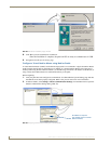
On your PC, click Start > Run to open the Run dialog.
Enter cmd into the Open field and click OK to open the command DOS prompt.
From the C:\> command line, enter ipconfig to display the IP Address of the PC. This information
is entered into the Master IP/URL field on the panel.
9. Click OK three times to close the open dialogs, save your settings, and return to the main NetLinx Studio
application.
10. Click the OnLine Tree tab in the Workspace window to view the devices on the Virtual System. The
default System value is one.
11. Right-click on the Empty Device Tree/System entry and select Refresh System to re-populate the list.
12. Connect the terminal end of the PS4.4 power cable to the 12 VDC power connector on the side of the
stand-alone touch panel.
When configuring your panel to communicate with a Virtual Master (on your PC) via
wireless Ethernet, the Master IP/URL field must be configured to match the IP
Address of the PC and make sure to use the Virtual System value assigned to the
Virtual Master within NetLinx Studio.
FIG. 40 Assigning Communication Settings and TCP/IP Settings for a Virtual Master
Enter this IP
into the
Master IP/URL
field on the
System Settings
page
IP Addresses of computer
(also obtained by using the
Start > Run > cmd command)