


Installation
34
NXD-700Vi 7" Modero® Wall/Flush Mount Touch Panel with Intercom
7. Disconnect the terminal end of the power cable from the power supply.
8. Carefully slide the main unit into the cutout until the Mounting Tabs of the NXD-700Vi unit lie flush
against the wall.
9. Insert and secure four #4-40 Mounting Screws (included) into their corresponding holes located along the
sides of the NXD-700Vi (using a grounded Phillips-head screwdriver) until the unit is secure and flush
against the wall (FIG. 16).
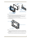
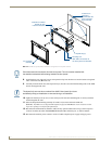
10. Place the Faceplate/Trim Ring assembly (A in FIG. 16) back onto the main unit (B in FIG. 16). Make sure
to align the Microphone, Light, and PIR Motion sensor locations to their respective openings on the front
bezel/faceplate.
11. Reconnect the terminal RJ-45, Ethernet, USB, and any optional audio/video wiring to their respective
locations on either the NXA-AVB/ETHERNET Breakout Box, Ethernet port, or NetLinx Master.
12. Reconnect the terminal power connector on the 12 VDC-compliant power supply and apply power.
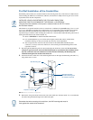
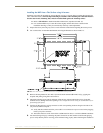
Installing an NXD-700Vi into an (optional) Rack Mount Kit (NXA-RK7)
The NXA-RK7 is a 19" (48.3 cm) wide metal rack-mount (with black matte finish) measuring 4 rack units
high.
1. Remove the Faceplate/Trim Ring assembly from the main NXD-700Vi unit.
2. Thread the incoming power, RJ-45 audio/video, Ethernet, and USB wiring (from their terminal sources)
through the surface opening, leaving enough slack in the wiring to accommodate any re-positioning of the
panel.
3. Connect all data and power wiring connectors to their corresponding locations along the left side of the
(un-powered) NXD touch panel.
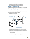
Verify that the terminal end of the power cable is not connected to the a power supply before
plugging in the 2-pin power connector.
The USB connectors can be from a either a USB extension cable, or a wireless USB RF transmitter.
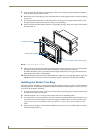
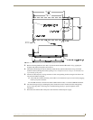
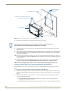
FIG. 16 Wall Mount panel installation configuration for flat surfaces
B - Main NXD-700Vi unit
Install the four #4-40 Mounting Screws
Flat installation surface
Mounting Tab
Attachment is done
along the edges
of the cutout
(included) into these four holes
Don’t disconnect the connectors from the touch panel. The unit must be installed with
the necessary connectors before being inserted into the solid surface.