


Introduction
5
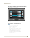
NXD-700Vi 7" Modero® Wall/Flush Mount Touch Panel with Intercom
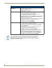
Product Specifications (Cont.)
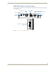
Side Panel Components:
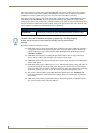
Front setup access button: • Provides both access to the Setup and Calibration page and toggles the
panel between a "sleep" or "wake" state.
- When wired, "sleep" status means the backlight is Off.
- When battery operated, wireless "sleep" status means the touch panel
base is either Off or "suspended".
Microphone: • Used for intercom applications
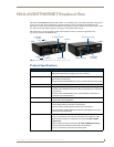
(requires the NXA-AVB/ETHERNET Breakout Box for analog
communication)
Speaker: • Single 2 watt speaker
LEDs • 2 blue LEDs (support On and Off)
- Both the LEDs and pushbuttons are only available when using the default
Button Trim Ring on the NXD panel.
Buttons • 2 programmable pushbuttons
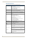
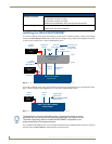
Mini-USB connector: • 5-pin Mini-USB connector used for programming, firmware update, and touch
panel file transfer between the PC and the target panel.
Note: When connecting the panel to PC using a CC-USB (or compatible)
cable, be sure to power the panel On before attempting to connect the USB
cable from the PC to the mini-USB port on the panel.
Stereo Output connector: • Stereo output through a 3.5mm mini-jack (for use with external speakers or
headphones).
Ethernet 10/100 port: • RJ-45 port for 10/100 Mbps communication. The Ethernet port automatically
negotiates the connection speed (10 Mbps or 100 Mbps), and whether to use
half duplex or full duplex mode.
• NXD-700Vi panels communicate with the NetLinx Master using the ICSP
protocol over Ethernet.
Ethernet 10/100 LEDs: • LEDs show communication activity and connection information:
A-activity - Yellow LED lights when receiving or transmitting Ethernet data
packets.
L-link - Green LED lights when the Ethernet cables are connected and
terminated correctly.
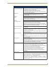
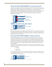
USB connector: • Type-A USB port can connect an external keyboard or mouse device for use
with Virtual PC applications.
Note: External USB input devices (keyboard or mouse) must be plugged into
the rear/side USB connector before the unit is powered-up. The panel will not
detect these USB input devices until the unit cycles power.
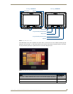
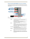
Audio/Video connector: • RJ-45 connector for communication of differential audio/video signals
to/from the touch panel (panel type dependant). This connector receives
Composite video, Stereo (left/right) audio, and microphone audio.
• Video is received via the NXA-AVB/ETHERNET Breakout Box. Configuring
video windows for playback is done using TPDesign4.
• In-bound audio (from the breakout box) gets directed to the speakers.
• Out-bound audio is sent from the on-board microphone (on the
front-panel). Selecting audio files for playback is configured through
TPDesign4.
PWR connector: • 2-pin 3.5 mm mini-Phoenix connector.
Button Assignments: Button assignments can only be adjusted in TPD4 and not on the panels.
• Button channel range: 1 - 4000 button push and feedback (per address port)
• Button variable text range: 1 - 4000 (per address port)
• Button states range: 1 - 256 (General Button; 1 = Off State, 2 = On State)
• Level range: 1 - 600 (default level value 0-255, can be set up to 1-65535)
• Address port range: 1 - 100