


Installation
36
NXD-700Vi 7" Modero® Wall/Flush Mount Touch Panel with Intercom
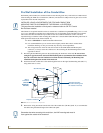
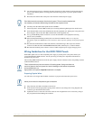
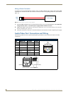
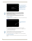
Wiring a Power Connection
To use the 2-pin 3.5 mm mini-Phoenix connector with a 12 VDC-compliant power supply, the incoming PWR
and GND wires from the external source must be connected to their corresponding locations on the connector
(FIG. 17).
1. Insert the PWR and GND wires on the terminal end of the 2-pin 3.5 mm mini-Phoenix cable. Match the
wiring locations of the +/- on both the power supply and the terminal connector.
2. Tighten the clamp to secure the two wires. Do not tighten the screws excessively; doing so may strip the
threads and damage the connector.
3. Verify the connection of the 2-pin 3.5 mm mini-Phoenix to the external 12 VDC-compliant power supply.
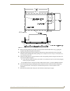
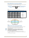
Audio/Video Port: Connections and Wiring
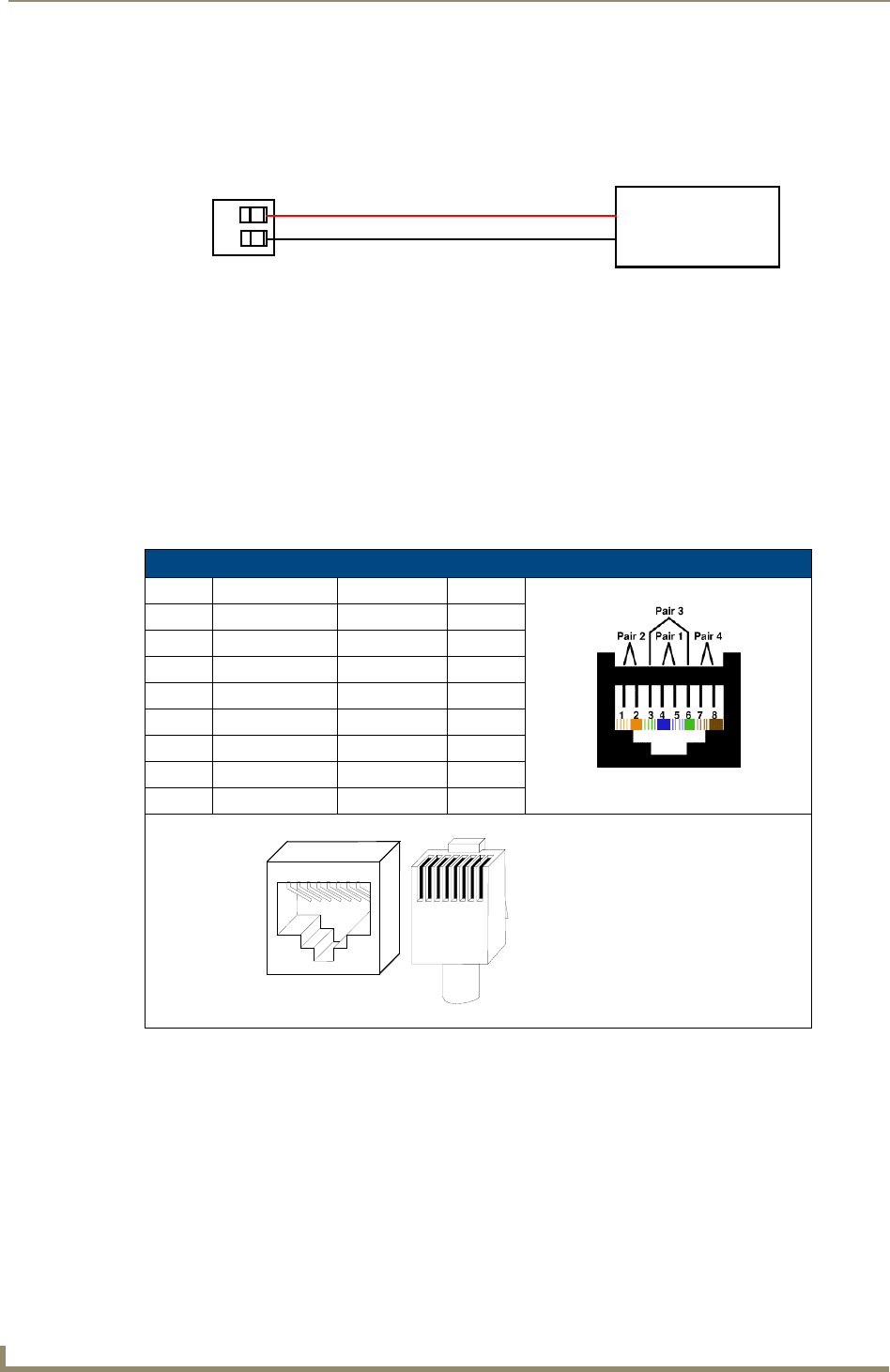
The following table shows the signal and pinout/pairing information used on the RJ-45 Audio and Video
connections.
FIG. 17 NetLinx power connector wiring diagram
Audio/Video RJ-45 Pinout Information
Pin Wire Color Function Polarity
1 Orange/White Right Audio In +
2 Orange Right Audio In -
3 Green/White Video In -
4 Blue Mic Out -
5 White/Blue Mic Out +
6 Green Video In +
7 White/Brown Left Audio In +
8 Brown Left Audio In -
PWR +
GND -
To the Touch Panel
Power Supply
TIA 568B
1
2
3
4
5
6
7
8
1 2 3 4 5 6 7 8
RJ-45 connector - pin configurations
(female) (male)