


Installation
35
NXD-700Vi 7" Modero® Wall/Flush Mount Touch Panel with Intercom
4. Test the incoming wiring by connecting the panel connections to their terminal locations and applying
power. Verify that the panel is receiving power and functioning properly to prevent repetition of the
installation.
5. Disconnect the terminal end of the power cable from the connected power supply.
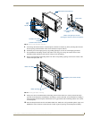
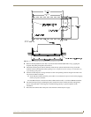
6. Carefully insert the NXD-700Vi panel into the NXA-RK7.
7. Secure the panel to the NXA-RK7 mount by first inserting and then tightening the four #4-40 screws.
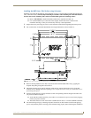
8. Insert the NXA-RK7 (with connected NXD unit) into the equipment rack, making sure to align the screw
holes along the sides on the NXA-RK7 with the holes in the equipment rack.
9. Use a grounded Phillips-head screwdriver to secure the NXA-RK7 to the equipment rack using
#10-32 screws (included).
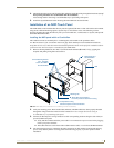
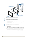
10. Place the Faceplate/Trim Ring assembly back onto the main NXD unit. Make sure to align the
Microphone, Light, and PIR Motion sensor locations to their respective openings on the front faceplate/
bezel.
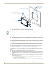
11. Reconnect the terminal RJ-45 audio/video, Ethernet, and USB wiring to their respective terminal
locations on either the NXA-AVB/ETHERNET Breakout Box, Ethernet port, or NetLinx Master.
12. Reconnect the terminal power connector on the 12 VDC-compliant power supply and apply power.
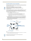
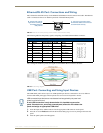
Wiring Guidelines for the NXD-700Vi Panels
NXD-700Vi panels use a 12 VDC-compliant power supply to provide power to the panel via the 2-pin
3.5 mm mini-Phoenix PWR connector. Use the previously provided power requirement information to
determine the power draw.
The incoming PWR and GND wires from the power supply must be connected to the corresponding locations
within the PWR connector.
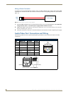
Preparing Captive Wires
You will need a wire stripper and flat-blade screwdriver to prepare and connect the captive wires.
1. Strip 0.25 inch (6.35 mm) of insulation off all wires.
2. Insert each wire into the appropriate opening on the connector (according to the wiring diagrams and
connector types described in this section).
3. Tighten the screws to secure the wire in the connector. Do not tighten the screws excessively; doing so
may strip the threads and damage the connector.
Don’t disconnect the connectors from the touch panel. The unit must be installed with
the necessary connectors before being inserted into the equipment rack.
These units should only have one source of incoming power. Using more than one
source of power to the touch panel can result in damage to the internal components
and a possible burn out.
Apply power to the panels only after installation is complete.
Never pre-tin wires for compression-type connections.