


Installation
31
NXD-700Vi 7" Modero® Wall/Flush Mount Touch Panel with Intercom
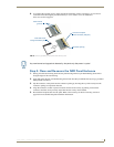
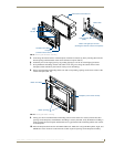
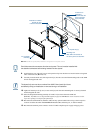
3. Remove the Faceplate/bezel (A in FIG. 14) from the main NXD unit (B in FIG. 14) by gripping the
faceplate and pulling with gentle outward force.
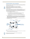
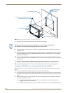
4. Thread the incoming power, RJ-45, Ethernet, USB, and any optional audio/video wiring (from their
terminal locations) through the surface opening. Leave enough slack in the wiring to accommodate any
re-positioning of the panel.
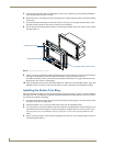
5. Connect all data and power wiring connectors to their corresponding locations along the left side of the
(un-powered) NXD touch panel.
Verify that the terminal end of the power cable is not connected to a power source before plugging
in the 2-pin power connector.
The USB connectors can be from a either a USB extension cable, or a wireless USB RF transmitter.
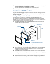
6. Test the incoming wiring by attaching the panel connections to their terminal locations and applying
power. Verify the panel is receiving power and functioning properly to prevent repetition of the
installation.
7. Disconnect the terminal end of the power cable from the connected power supply.
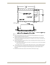
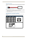
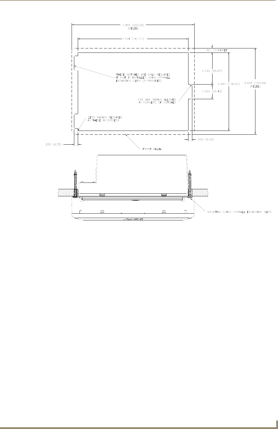
FIG. 13 NXD-700Vi Wall Mount panel dimensions using expansion clips