


Installation
29
NXD-700Vi 7" Modero® Wall/Flush Mount Touch Panel with Intercom
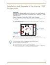
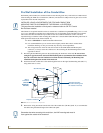
4. Thread the incoming power, RJ-45 audio/video, Ethernet, and USB wiring through the knockouts (use of
the left wiring knockouts are recommended with this installation).
Leave enough slack in the wiring to accommodate any re-positioning of the panel.
5. Install the drywall/sheetrock before inserting the main NXD unit into the CB-TP7.
Installation of an NXD Touch Panel
The NXD-700Vi can be installed either directly into the (optional) CB-TP7 or other solid surface environment
using the two different mounting options: drywall clips or solid surface screws. The following sections
describe mounting the touch panel directly into a pre-wall conduit box, a solid surface or drywall, and optional
NXA-RK7 Rack Mount Kit.
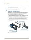
Installing the NXD panel within a Conduit Box
The conduit box must be mounted prior to continuing this section. Refer to the procedures in the
Pre-Wall Installation of the Conduit Box section on page 28 for detailed pre-wall installation instructions.
Verify that all necessary cables have been threaded through the knockouts on the left of the conduit box and the
connections have been tested prior to installation of the NXD-700Vi.
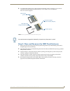
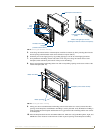
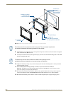
1. Remove the Faceplate/bezel (A in FIG. 12) from the main NXD unit (B in FIG. 12) by gripping the
faceplate and pulling with gentle outward force.
2. Verify the incoming power, RJ-45 audio/video, Ethernet, and USB cables have been properly threaded
through the wiring knockouts on the left of the conduit box. Leave enough slack in the wiring to
accommodate any re-positioning of the panel.
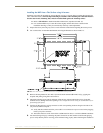
3. Connect all data and power wiring connectors to their corresponding locations along the side of the (un-
powered) NXD touch panel.
Verify that the terminal end of the power cable is not connected to a power source before plugging
in the 2-pin power connector.
The USB connectors can be from either a USB extension cable, or a wireless USB RF transmitter.
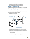
4. Test the incoming wiring by connecting the panel connections to their terminal locations and applying
power. Verify that the panel is receiving power and functioning properly to prevent repetition of the
installation.
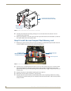
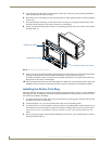
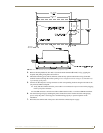
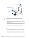
FIG. 12 NXD-700Vi panel installation into a CB-TP7 (pre-wall construction)
B - Main NXD unit consists of
C - Optional CB-TP7
#4-40 Mounting Screws
(four - included)
secure the NXD to
Stud
the touch panel and back box housing
conduit/wallbox
A - Faceplate/Trim Ring
default Faceplate comes with buttons
the Conduit Box
Mounting Tab