


NEAX2000 IVS
2
ISDN System Manual
Page iv ND-70919 (E), Issue 1.0
LIST OF FIGURES
Figure Title Page
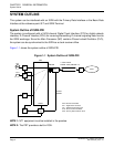
Figure 1-1 System Outline of ISDN-PRI . . . . . . . . . . . . . . . . . . . . . . . . . . . . . . . . . . . . . . . . . . . . 4
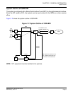
Figure 1-2 System Outline of ISDN-BRI . . . . . . . . . . . . . . . . . . . . . . . . . . . . . . . . . . . . . . . . . . . . 5
Figure 1-3 Example of ISDN-VPN (1 of 2) . . . . . . . . . . . . . . . . . . . . . . . . . . . . . . . . . . . . . . . . . . 6
Figure 1-3 Example of ISDN-VPN (2 of 2) . . . . . . . . . . . . . . . . . . . . . . . . . . . . . . . . . . . . . . . . . . . 7
Figure 1-4 System Outline of ISDN Terminal (for ISDN-PRI) . . . . . . . . . . . . . . . . . . . . . . . . . . . . 8
Figure 1-5 System Outline of ISDN Terminal (for ISDN-BRI) . . . . . . . . . . . . . . . . . . . . . . . . . . . . 9
Figure 1-6 Clock Supply Route . . . . . . . . . . . . . . . . . . . . . . . . . . . . . . . . . . . . . . . . . . . . . . . . . . . 12
Figure 1-7 System Outline of Event Based CCIS . . . . . . . . . . . . . . . . . . . . . . . . . . . . . . . . . . . . . 14
Figure 1-8 Release Timing of Virtual Tie Line and CCIS Link . . . . . . . . . . . . . . . . . . . . . . . . . . . . 15
Figure 1-9 Virtual Trunk . . . . . . . . . . . . . . . . . . . . . . . . . . . . . . . . . . . . . . . . . . . . . . . . . . . . . . . . 16
Figure 1-10 Accommodation of DTI/DCH/ICH/BRT/PRT into TDSW . . . . . . . . . . . . . . . . . . . . . . . 24
Figure 1-11 Time Slot Allocation for DTI . . . . . . . . . . . . . . . . . . . . . . . . . . . . . . . . . . . . . . . . . . . . . 25
Figure 1-12 Line Distance Between PBX and NT1/ISDN Terminal . . . . . . . . . . . . . . . . . . . . . . . . 26
Figure 1-13 DTI Frame Configuration (12-Multi Frame) . . . . . . . . . . . . . . . . . . . . . . . . . . . . . . . . . 29
Figure 1-14 DTI Frame Configuration (24-Multi Frame) . . . . . . . . . . . . . . . . . . . . . . . . . . . . . . . . . 31
Figure 1-15 Frame Configuration of 30DTI . . . . . . . . . . . . . . . . . . . . . . . . . . . . . . . . . . . . . . . . . . . 33
Figure 2-1 Static Electricity Guard (1 of 2) . . . . . . . . . . . . . . . . . . . . . . . . . . . . . . . . . . . . . . . . . . 36
Figure 2-1 Static Electricity Guard (2 of 2). . . . . . . . . . . . . . . . . . . . . . . . . . . . . . . . . . . . . . . . . . .36
Figure 2-2 Installation Procedure for ISDN-PRI . . . . . . . . . . . . . . . . . . . . . . . . . . . . . . . . . . . . . . 41
Figure 2-3 DTI/PRT Cable Connection via MDF . . . . . . . . . . . . . . . . . . . . . . . . . . . . . . . . . . . . . . 44
Figure 2-4 Location of AP Slots and LTC Connectors for DTI/PRT . . . . . . . . . . . . . . . . . . . . . . . 45
Figure 2-5 Example of MDF Cross Connection for DTI/PRT . . . . . . . . . . . . . . . . . . . . . . . . . . . . 46
Figure 2-6 Cable Connection via the CONN Card . . . . . . . . . . . . . . . . . . . . . . . . . . . . . . . . . . . . 47
Figure 2-7 Example of Coaxial Cable Connection . . . . . . . . . . . . . . . . . . . . . . . . . . . . . . . . . . . . 48
Figure 2-8 Installation Procedure for ISDN-BRI . . . . . . . . . . . . . . . . . . . . . . . . . . . . . . . . . . . . . . 49
Figure 2-9 BRT Cable Connection via MDF . . . . . . . . . . . . . . . . . . . . . . . . . . . . . . . . . . . . . . . . . 51
Figure 2-10 Location of AP Slots and LTC Connectors for BRT . . . . . . . . . . . . . . . . . . . . . . . . . . . 52
Figure 2-11 Example of MDF Cross Connection for BRT (1 of 2) . . . . . . . . . . . . . . . . . . . . . . . . . . 53
Figure 2-11 Example of MDF Cross Connection for BRT (2 of 2) . . . . . . . . . . . . . . . . . . . . . . . . . . 54
Figure 2-12 Installation Procedure for ISDN Terminal . . . . . . . . . . . . . . . . . . . . . . . . . . . . . . . . . . 55
Figure 2-13 ILC Cable Connection via MDF . . . . . . . . . . . . . . . . . . . . . . . . . . . . . . . . . . . . . . . . . . 58
Figure 2-14 Location of LT Slots and LTC Connectors for ILC . . . . . . . . . . . . . . . . . . . . . . . . . . . . 59
Figure 2-15 Example of MDF Cross Connection for ILC . . . . . . . . . . . . . . . . . . . . . . . . . . . . . . . . . 60
Figure 2-16 Installation Procedure for Event Based CCIS . . . . . . . . . . . . . . . . . . . . . . . . . . . . . . . 61
Figure 3-1 Outline of BRI to BRI Connections . . . . . . . . . . . . . . . . . . . . . . . . . . . . . . . . . . . . . . . 115
Figure 3-2 Event Based CCIS Programming Summary . . . . . . . . . . . . . . . . . . . . . . . . . . . . . . . . 116
Figure 3-3 Verification of Connection . . . . . . . . . . . . . . . . . . . . . . . . . . . . . . . . . . . . . . . . . . . . . . 127
Figure 4-1 Mounting Location of Circuit Card . . . . . . . . . . . . . . . . . . . . . . . . . . . . . . . . . . . . . . . . 139