


NEAX2000 IVS
2
ISDN System Manual
Page 154 ND-70919 (E), Issue 1.0
CHAPTER 4 CIRCUIT CARD INFORMATION
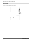
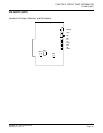
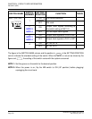
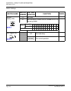
PN-2BRTC (BRT)
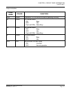
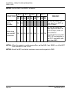
The figure in the SWITCH NAME column and the position in in the SETTING POSITION
column indicate the standard setting of the switch. When the switch is not set as shown by the
figure and , the setting of the switch varies with the system concerned.
NOTE 1: Set the groove on the switch to the desired position.
NOTE 2: When the power is on, flip the MB switch to ON (UP position) before plugging/
unplugging the circuit card.
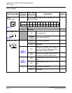
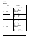
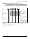
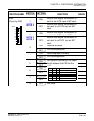
SW11 (DIP SW)
1
For normal operation
OFF Not used
2
NOTE 3
NOTE 4
ON
Output clock signals according to
the switch setting of SW11-3
OFF Do not output clock signals.
3
NOTE 3
NOTE 4
ON Output clock signals to PLO0 of MP
OFF Output clock signals to PLO1 of MP
4
ON AP No. 04-15
OFF AP No. 20-31
(Continued)
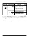
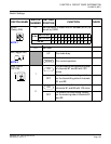
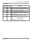
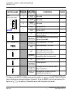
SWITCH NAME
SWITCH
NUMBER
SETTING
POSITION
FUNCTION CHECK
1
2
3
4
ON
ON