


NEAX2000 IVS
2
ISDN System Manual
Page 172 ND-70919 (E), Issue 1.0
CHAPTER 4 CIRCUIT CARD INFORMATION
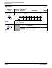
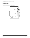
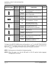
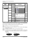
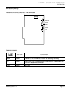
PN-24PRTA (PRT)
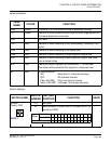
The figure in the SWITCH NAME column and the position in in the SETTING POSITION
column indicate the standard setting of the switch. When the switch is not set as shown by the
figure and , the setting of the switch varies with the system concerned.
NOTE 1: Set the groove on the switch to the desired position.
NOTE 2: When the power is on, flip the MB switch to ON (UP position) before plugging/
unplugging the circuit card.
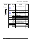
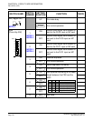
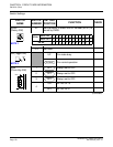
JPR0 (Jumper Pin)
UP
Neutral grounding on the receiving
line is provided.
Neutral grounding on the receiving
line is not provided.
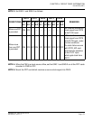
JPR1 (Jumper Pin)
Line impedance: 100 ohms
Left Line impedance: 110 ohms
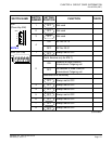
JPS (Jumper Pin)
UP
Neutral grounding on the
transmitting line is provided.
Neutral grounding on the
transmitting line is not provided.
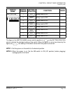
MAS (Jumper Pin)
UP Clock Source
Clock Receiver
AISS (Jumper Pin) AIS signal is sent out when make-
busy or power on.
DOWN
AIS signal is not sent out when
make-busy or power on.
(Continued)
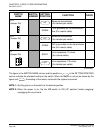
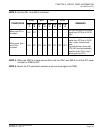
SWITCH NAME
SWITCH
NUMBER
SETTING
POSITION
FUNCTION CHECK
DOWN
Right
DOWN
DOWN
UP