ADJUNCT POWER
Connecting the Power Supply
The power output is provided through 3 modular jacks on the power supply. These jacks are
labeled, from left to right,
PHONE OTHER LINE
-7 +8 -2 +5
The - and + numbers under ‘‘PHONE’’ and ‘‘OTHER’’ refer to the pins on which power is present
and the polarity of that power.
The PHONE and LINE jacks are 8-pin female non-keyed 657-type jacks that can accept D4, D6,
and D8 modular plug cables. The OTHER jack is a 6-pin female non-keyed 657-type jack.
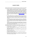
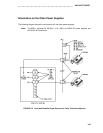
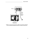
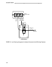
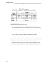
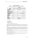
The following local powering arrangements, shown in Figures 1 and 2, can be used with the
MSP-1 power supply.
Figure 1 shows the local powering arrangement for: ISDN voice terminals; the DCP 7444
and 8434 voice terminals’ VF displays; and adjuncts connected to all telephones except
the 8102.
Figure 2 shows the local powering arrangement for adjuncts connected to the 8102 tele-
phone.
Note: The type of cord(s) needed to make these connections are designated in each draw-
ing.
2-36


