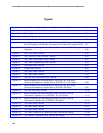
Figure 5-2. The 7400B Plus Data Module ………………………………………………………… 5-10
Figure 5-2. Block Diagram of the 7400B Interface ………………………………………………… 5-12
Figure 5-3. The 8400B Plus Data Module ………………………………………………………… 5-18
Figure 5-2. Typical Installation of the U.S. Configuration, including Telephone and
Separate Power Supply ………………………………………………………………… 5-19
Figure 5-3. Typical Installation of the International Configuration, including Telephone
and Separate Power Supply …………………………………………………………… 5-20
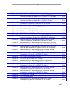
Figure 5-4. Typical Installation of the U.S. and International Configuration, including
Telephone and Closet Power Supply ………………………………………………… 5-21
Figure 5-5. The 7500B Data Module ……………………………………………………………… 5-28
Figure 5-6. Digital Terminal Data Module mounted on a 7405D Voice Terminal ……………… 5-36
Figure 5-2. Block Diagram of DTDM Interfaces …………………………………………………… 5-37
Figure 5-3. The Optional Z702AL1 Data Service Unit shown with 7407D01B Voice Terminal 5-42
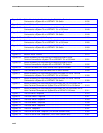
Figure 5-2. Block Diagram of Z702AL1 Data Service Unit Interfaces …………………………… 5-43
Figure 5-3. The 703A Data Service Unit …………………………………………………………… 5-47
Figure 5-2. Block Diagram of 703A Data Service Unit …………………………………………… 5-49
Figure 5-3. The DEFINITY High Speed Link ……………………………………………………… 5-53
Figure 5-2. Switched Network Application ………………………………………………………… 5-58
Figure 5-3. Permanent (Private Line) Applications………………………………………………… 5-60
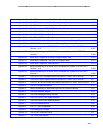
Figure 5-4. The Processor Data Module (stand-alone model) …………………………………… 5-63
Figure 5-5. The Trunk Data Module (stand-alone model) ………………………………………… 5-68
Figure 5-6. The MTDM, the Stand-alone model …………………………………………………… 5-72
Figure 5-7. The 3270A or 3270T Data Module …………………………………………………… 5-77
Figure 5-2. 3270C Data Module …………………………………………………………………… 5-80
Figure 5-3. The Z3A Asynchronous Data Unit …………………………………………………… 5-85
xxx


