


CALLMASTER and CALLMASTER II and III Voice Terminals
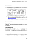
Distance Limitations
The maximum allowable distances the CALLMASTER voice terminals can be located from the
DEFINITY G1, G2, G3, System 75, or System 85 cabinet is shown in the table below.
NOMINAL MAXIMUM RANGE
IN FEET (METERS) (SEE NOTE)
SYSTEM PORT BOARD
24 AWG 26 AWG
DEFINITY G2 SN270B 3,400 (1,034) 2,200 (671)
SYSTEM 85 TN754 3,400 (1,034) 2,200 (671)
DEFINITY G1 & G3
SYSTEM 75 TN754 3,400 (1,034) 2,200 (671)
Note: These ranges can be extended to 5,000 feet (1524 m) for 24 AWG wire and 4,000
feet (1219 m) for 26 AWG wire with the use of a Data Link Protector (DLP). Refer to
EXPOSED PORT PROTECTION.
In 2-wire installations, the CALLMASTER III can be connected to a TN2181 port
board.
Power Requirements
The CALLMASTER voice terminals receive power from the system and do not require any exter-
nal power supply. However, adjunct equipment connected to the CALLMASTER II or III needs its
own power supply.
Switch Administration
The 602 CALLMASTER and CALLMASTER II and III can be used with DEFINITY G1, G2, G3,
System 75 (R1V3) and System 85 (R2V2 through R2V4). The 602 CALLMASTER can be
administered as itself. The CALLMASTER II and the CALLMASTER III must then be aliased as
a 602 CALLMASTER.
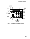
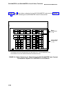
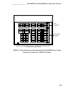
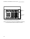
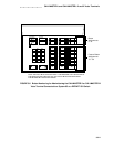
Button Numbering
The following button diagrams of the 602 CALLMASTER and CALLMASTER II and III voice ter-
minals will help you administer both of these voice terminals connected to a System 75 (R1V3 or
later) or DEFINITY G1 and G3 and to a System 85 (R2V2 or later) or DEFINITY G2.
3-307