


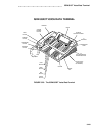


ISDN 8510T Voice/Data Terminal
Recommended power supplies are the MSP-1 (local) Power Supply and the 1145A Bulk Power
Supply.
Terminating Resistors
The terminating resistor jumpers are located on the upper left side on the bottom of the terminal.
Above the pins, on the plastic housing, you will see the label TERM RESISTOR and a diagram of
the correct settings.
These jumpers enable (ON) or bypass (OFF) the terminating resistor. The set is shipped with the
jumpers in the OFF position bypassing the terminating resistor. You must verify that the jumper
settings are set correctly for your configuration.
Note: The terminating resistor jumpers must be set
only
by qualified service personnel.
The terminating resistor jumpers must be set to OFF when the set is in a point-to-point
configuration and the terminating resistor is in the closet or a 440A4 is connected on the
line. When set to OFF, each of the two terminating resistor jumpers covers the two top
pins in each set. (The bottom pin in each set is left uncovered.)
The terminating resistor jumpers must be set to ON when the set is in a point-to-point
configuration and the terminating resistor is
not
in the closet or a 440A4 is
not
connected
to the line. When set to ON, each of the two terminating resistor jumpers covers the two
lower pins in each set. (The top pin in each set is left uncovered.)
The terminating resistor jumpers must be set to OFF when the set is in a multipoint confi-
guration and the terminating resistor is in the closet, a 440A4 is connected on the line, or
the jumper is set to ON in one of the other sets on the line. When set to OFF, each of
the two terminating resistor jumpers covers the two top pins in each set. (The bottom pin
in each set is left uncovered.)
The terminating resistor jumpers must be set to ON when the set is in a multipoint confi-
guration and the terminating resistor is
not
in the closet, a 440A4 is not connected on the
line, or the jumper is not set to ON in any of the other sets on the line. When set to ON,
each of the two terminating resistor jumpers covers the two lower pins in each set. (The
top pin in each set is left uncovered.)
3-426