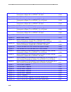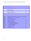
Figure 3-43. Button Numbering for Administering the 7444 Voice Terminal
Connected to a System 85 or a DEFINITY G2 Switch ……………………………… 3-232
Figure 3-44. The 8403 Voice Terminal ……………………………………………………………… 3-237
Figure 3-45. Button Numbering for Administering the 8403 Voice Terminal
Connected to a System 75 or a DEFINITY G1 or G3 Switch ……………………… 3-248
Figure 3-46. Button Numbering for Administering the 8403 Voice Terminal
Connected to a System 85 or a DEFINITY G2 Switch ……………………………… 3-249
Figure 3-47. 8410D Voice Terminal (With Display) ………………………………………………… 3-253
Figure 3-48. Button Numbering for Administering the 8410 Voice Terminal
Connected to a System 75 or a DEFINITY G1 or G3 Switch ……………………… 3-268
Figure 3-49. Button Numbering for Administering the 8410 Voice Terminal
Connected to a System 85 or a DEFINITY G2 Switch ……………………………… 3-269
Figure 3-50. 8434 Voice Terminal …………………………………………………………………… 3-274
Figure 3-51. 8434DX Voice Terminal ………………………………………………………………… 3-275
Figure 3-52. Button Numbering for Administering the 8434 and 8434DX Voice
Terminal Connected to a System 75 or a DEFINITY G1 or G3 Switch …………… 3-291
Figure 3-53. Button Numbering for Administering the 8434 and 8434DX Voice
Terminal Connected to a System 85 or a DEFINITY G2 Switch …………………… 3-292
Figure 3-54. The 602 CALLMASTER Voice Terminal with Optional Handset …………………… 3-298
Figure 3-2. The CALLMASTER II and CALLMASTER III Voice Terminal ……………………… 3-299
Figure 3-3. Button Numbering for Administering the 602 CALLMASTER Voice Terminal
Connected to a System 75 or a DEFINITY G1 or G3 Switch ……………………… 3-308
Figure 3-4. Button Numbering for Administering the 602 CALLMASTER Voice Terminal
Connected to a System 85 or a DEFINITY G2 Switch ……………………………… 3-309
Figure 3-5. Button Numbering for Administering the CALLMASTER II or CALLMASTER III
Voice Terminal Connected to a System 75 or a DEFINITY G1 or G3 Switch …… 3-310
Figure 3-6. Button Numbering for Administering the CALLMASTER II or CALLMASTER III
Voice Terminal Connected to a System 85 or a DEFINITY G2 Switch …………… 3-311
Figure 3-7. The 500 Series Telephone……………………………………………………………… 3-315
Figure 3-8. The 2500 DMGC Telephone …………………………………………………………… 3-327
Figure 3-9. The 2500 YMGK Telephone …………………………………………………………… 3-333
Figure 3-10. The 2500 MMGL Telephone …………………………………………………………… 3-339
Figure 3-11. The 2500 YMGL Telephone …………………………………………………………… 3-340
Figure 3-12. The 8101 Telephone …………………………………………………………………… 3-347
Figure 3-13. The 8102 and 8102M Telephone (The 8102M is shown here)……………………… 3-355
Figure 3-14. The 8110 and 8110M Telephones (The 8110M is shown here) …………………… 3-367
xxviii


