


Installation Procedures
Before installing the system, read the safety instructions
on page C-1. To prevent damage to the system or
installation location, the environmental and electrical
conditions must meet the specifications in Appendix B.
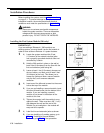
WARNING:
There are no customer-serviceable components
inside the system modules. There are hazardous
voltages within that can cause severe or fatal
personal injury. DO NOT OPEN THE MODULES.
Installing the First System Module (206 only)
IMPORTANT:
If you are adding a Release 4.1 206 module to an
existing system, you must install it as the first module in
order to have access to Release 4.1 system features.
1
2
3
A)
B)
C)
A)
B)
C)
A)
B)
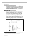
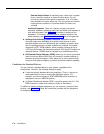
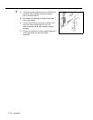
Locate the system module within 5 feet
(1.5 meters) of the network interface jacks
and a properly grounded electrical outlet not
controlled by a switch.
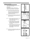
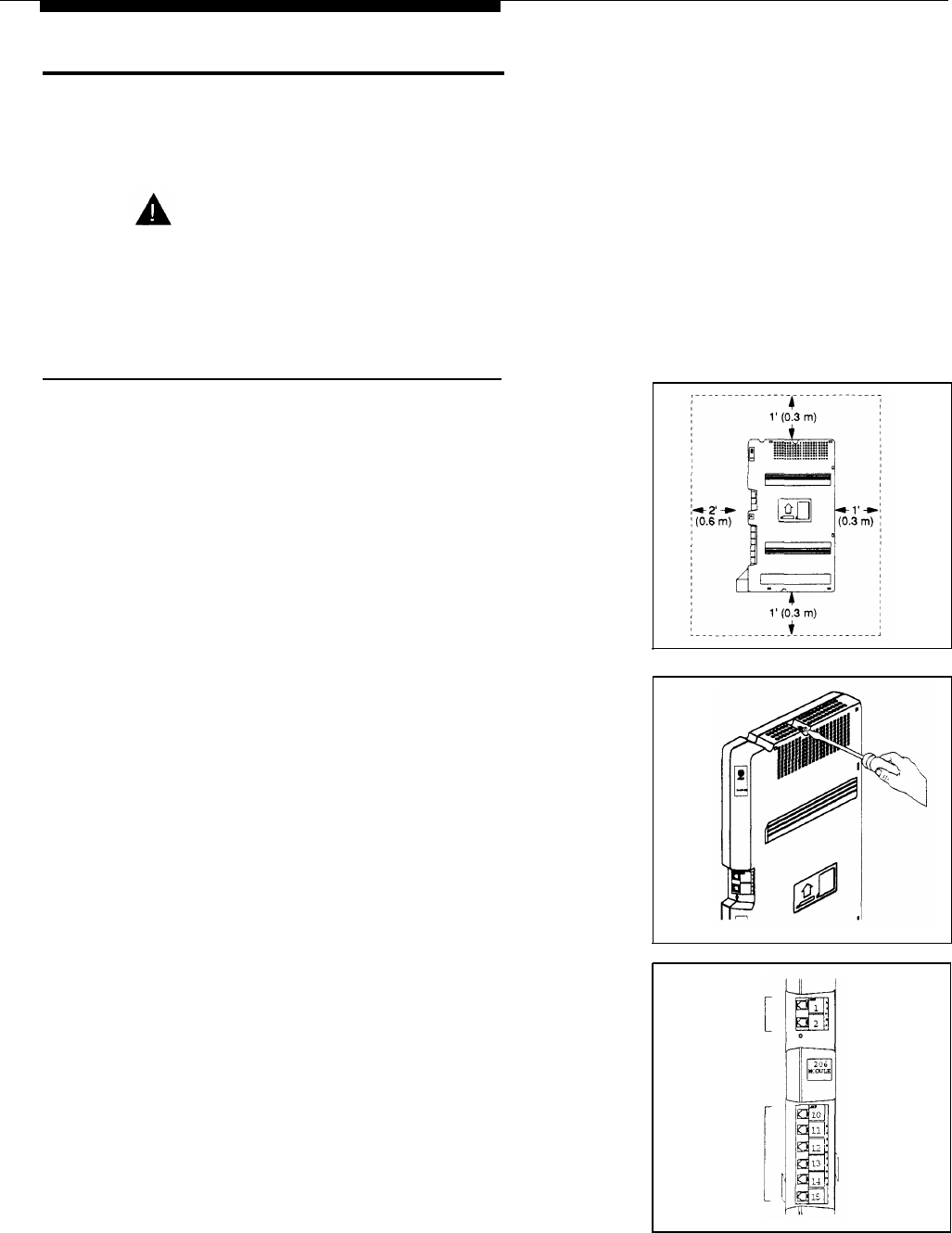
Hold the 206 module in place on the wall at
least 2 feet (0.6 meters) from the floor with the
line and extension jacks facing left.
Leave at least 1 foot (0.3 meters) clearance at
the top, bottom, and back, and at least 2 feet
(0.6 meters) at the front. This allows you to
access the jacks and slide a second module
onto the first, and it ensures adequate
ventilation.
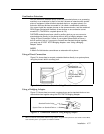
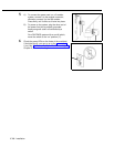
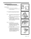
Insert one of the #8 wood screws into the screw
hole at the top of the module.
If you are not installing a second module, insert
the other #8 wood screw into the bottom of the
module. If you are installing a second
module, do not screw in the bottom of the
module at this time.
Tighten the screw(s) until the module is snug
against the wall. There must be a 3/8" (1 cm.)
gap between the wall and the rest of the
module. Do not overtighten—the module will
warp and fail to operate.
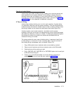
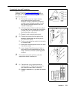
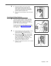
Label the line and extension jacks as shown.
If you are installing a 2-module system, go to
Step 1 of “Installing a Second Module;”
otherwise, go to Step 5 of that procedure.
Lines
Extensions
C-8 Installation