


8-8 Issue 2 December 1995
Switch Integration Device Administration
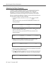
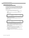
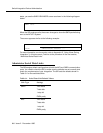
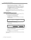
starts, you see the SMDI VIEW MODE screen as shown in the following diagram.
below:
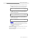
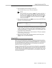
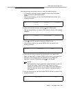
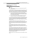
When the SID receives calls, the screen changes to show the SMDI packet being
sent to the INTUITY System.
The screen appears similar to the following example:
For more information on view modes, refer to Appendix B, "Using Views During
Integration", in this document. Continue to the procedure in the next section,
“Administer Serial Data Links.”
Administer Serial Data Links
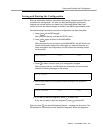
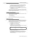
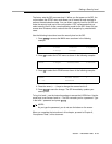
The SID assigns default configurations to both the MCI and SMDI communication
ports. You need to check the SID to make sure the defaults are set correctly and
match the requirements of your integration. The SID sets the defaults shown in
Table 8-1 for the serial data links.
SMDI Idle
SMDI MWI: 0OP:MWI 0000202!.
CPID: ..MD0010001D 0000201 ...
Table 8-1. Serial Data Link Default Values
Link Type Settings
SMDI: 1200 baud
7 data bits
1 stop bit
EVEN parity
MCI: 1200 baud
7 data bits
1 stop bit
EVEN parity