


4-6 Issue 2 December 1995
Hardware Installation
NOTE
:
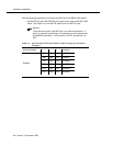
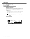
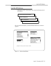
Recommended Default Settings:
■ If you use port 0, configure switches 01 and 02. If you use
port 1, configure switches 11 and 12.
■ Standard switch settings for SW01 or SW11 are 1 ON, 2 OFF,
3 ON, 4 OFF, 5 OFF, 6 OFF, 7 ON, and 8 ON.
■ Standard switch settings for SW02 or SW12 are 1 ON, 2 ON,
3 ON, 4 ON, 5 ON, 6 ON, 7 ON, and 8 OFF.
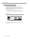
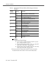
3. Connect one end of a 25-pair cable to the MCI I/O port on the switch.
To create the cable, refer to Table 4-4 for the correct cable pinouts.
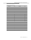
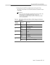
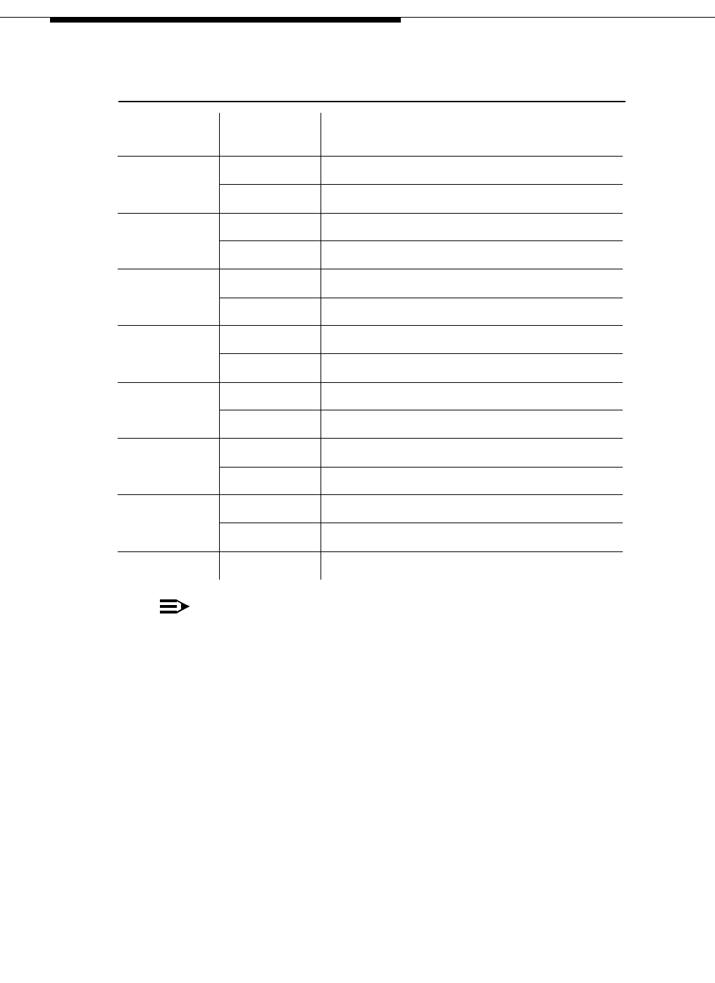
Table 4-3. MCI I/O Port DIP-Switch SW02 or SW12 Settings for Switches 1
through 8
Switch
Number
Setting Function
1
ON When PB lead is - terminal is busy
OFF When PB lead is + terminal is busy
2
ON DTR signal is always ON
OFF DTR signal is controlled by the CPU
3
ON DSR signal is not provided
OFF DSR signal is provided
4
ON CD is not provided
OFF CD is provided
5
ON CS is not provided
OFF CS is provided
6
ON CI is not provided
OFF CI is provided
7
ON PB signal is not provided
OFF PB signal is provided
8 OFF Not used