


1-4 Issue 2 December 1995
Introduction and Requirements for Integration
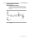
Determining the Placement of the SID
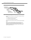
The Switch Integration Device (SID) and the MAP/5, MAP/40, or MAP/100
represent
local
devices. Place the SID and the MAP in the same area and close
enough together so the RS-232 cable supplied with the SID can connect to the
computer. During installation, the AT&T technician will place the SID and the
MAP in the location specified by the customer.
For the link between the MCI port and the INTUITY System, AT&T uses an
Electronic Industries Association (EIA) RS-232-C serial data electrical interface.
AT&T supplies an EIA standard RS-232 cable with a 25-pin connector. You
cannot directly connect the cable to the switch. The MCI port on the backplane of
the switch has a 25-pair connector. AT&T supplies the 25-pair to 25-pin adaptor
required to connect the RS-232 cable to the backplane of the switch. The
customer or the switch vendor representative must connect the adaptor to the
switch. AT&T assumes responsibility only for the RS-232 cable that connects to
the SID.
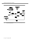
If the distance from the switch to the SID is longer than the RS-232 cable
reaches, you, the customer, must supply a cable that attaches between the AT&T
supplied cable and the NEAX 2400 MCI port adaptor. Use a cable that meets the
EIA RS-232 standards, including the 50 feet maximum cable length. Failure to
meet EIA communication standards may cause data transmission errors. If you
cannot reach the switch with the 50 feet maximum cable length, you, the
customer, must determine and engineer a method of connecting the SID and the
switch, such as using a limited-distance modem. AT&T does not recommend any
particular methods.