2-2 Issue 2 December 1995
Switch Integration Device Basics
The Switch Integration Device
Hardware
Before you use the SID, you need to understand each hardware component.
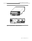
Read the descriptions below of each component and refer to Figure 2-1. to
locate the component.
Front Panel
Rear Panel
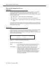
Continue to the next section, “Using the SID Software,” for an explanation of how
to use the SID displays and menus.
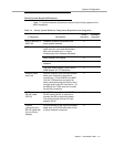
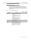
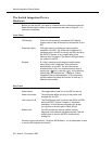
LCD display A two-line, 40-character, backlighted LCD display
screen used to show all menus and information on the
SID.
Diagnostic lights LED lights used to indicate and trace possible
problems in the SID. The LEDs help to determine if
problems exist in the SID, the link to the PBX, the link to
the INTUITY System, or any combination of the
different links or systems. The Status LED lights when
you power on the SID.
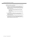
Keypad A 19-key, membrane-style keypad used to select
menu items, enter information, and perform all
administration on the SID. The keys include ten
numbered keys (0-9), four directional arrow keys, a
pound sign ( )key, a star key ( ), a Function key,
a Mode key, and an Enter key. Chapter 8, "Switch
Integration Device Administration", of this document
contains tables that show the function of each key, if
different than marked.
Power switch The toggle switch used to turn the SID on and off.
Power cord outlet The male outlet where you plug in the power cord
shipped with the SID.
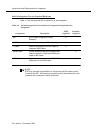
Link A and Link B Two RS-232 ports used to connect the SID to the PBX
and the INTUITY System. Chapter 4, "Hardware
Installation", of this document explains the proper
connections for the two ports. (Detail 25 pin)
Modem port The SID contains an internal modem used for
diagnostic and software upgrade purposes. Use the
modem port to connect the SID’s modem to an
analog line.
#
*


