


Issue 2 December 1995 7-13
Configuring the Message Center Interface Link
If you need more information for any of the screen fields or processes described
in this section, contact your switch administrator or consult the documentation
supplied with your switch.
Assign a Port for the Message Center
Interface Link
Use the instructions in this section to assign a port for the MCI link. Assigning a
port tells the switch the proper port to send information to the SID through the
MCI link.
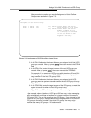
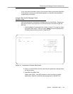
1. At the Installation Commands menu, shown in Figure 7-6., enter 1 to select
the System Data option. After you press you see the ASsignment
Of Station Data screen as shown in Figure 7-8.
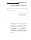
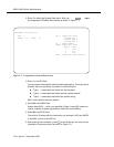
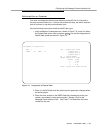
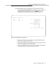
Figure 7-8. Assignment of System Data Screen
2. Enter 1 in the SYS field to tell the switch that the parameter changes effect
the entire system.
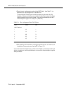
3. Enter 29 in the INDEX field.
System data (SYS) 1 uses 255 indexes to control a variety of system
parameters. Index 29 controls the port assignment for the MCI link.
ENTER
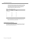
Assignment of System Data
SYS: 1 SYS : System Data Items
INDEX: 29 DATA: 02 1-System Data 1
2-System Data 2
3-System Data 3
TN : Tenant Number
INDEX: System Data Index
System Index
1 0-255
2 0-15
3 0-31
DATA : System Data (Hexa-decimal)