


Remote Annex 6300 Hardware Installation Guide
Appendix D Modem Upgrade Instructions
D-8
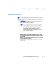
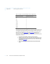
Table D-1. Modem Card/S1 DIP Switch Section Assignments
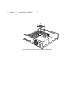
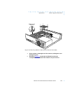
The following instructions detail how to remove a quad modem card
and toggle its appropriate DIP switch section (on DIP switch S1) to
assure that all remaining modem cards will be recognized by the
Remote Annex 6300.
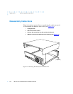
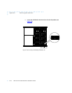
Figure D-5 and Figure D-6 illustrate the
instructions. These instructions assume that the cover of the unit has
already been removed.
1 Locate the quad modem card that you want to remove.
2 Starting at one corner of the card, push in the locking detent on the
nylon standoff, and gently work the corner of the card off the nylon
standoff (see
Figure D-5).
3 Repeat the procedure for the other three corners of the modem
card.
Modem Card Location DIP Switch Section (S1)
1-4 1
5-8 2
9-12 3
13-16 4
17-20 5
21-24 6
25-28 7
29-32 8