


A-3Remote Annex 6300 Hardware Installation Guide
Appendix A Port Pins and Signals
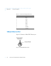
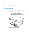
10Base5 Ethernet Port
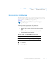
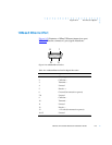
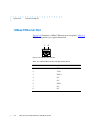
Figure A-3 illustrates a 10Base5 Ethernet transceiver port.
Table A-2 lists the connector’s pin/signal allocations.
Figure A-3. 10Base5 Ethernet Port
Table A-2. 10Base5 Ethernet Port Pin/Signal Allocation
81
915
Pin Number Signal
1 Chassis ground
2 Collision +
3 Transmit +
4 Unused
5 Receive +
6 Ground (for transceiver power)
7–8 Unused
9 Collision –
10 Transmit –
11 Unused
12 Receive –
13 + 12 volts (for transceiver power)
14–15 Unused